

pontoontodd
-
Posts
1783 -
Joined
-
Last visited
-
Days Won
34
Content Type
Profiles
Forums
Gallery
Store
Everything posted by pontoontodd
-
My first thought on the speedo was that Subarus are Legos so that should be simple. Unfortunately not. The automatic appears to use a 2 pin reluctor (VSS2) for the speedometer. The 6MT has a 3 pin Hall effect sensor VSS. First step was to wire the 6MT VSS to the Haltech (SPI4 in my case). From left to right looking at the wiring harness plug with the latch on top, colors are Haltech: pin 1 GyR (large/shielded, inner wire is orange) signal SPI4 pin 2 BW ground pin 3 GyR (small) +12VDC Have to calibrate it but that seemed to give us a vehicle speed on the Haltech. Need to take a picture. Next step is to set up one of the outputs of the Haltech to get the speedometer working. I think I know how just haven't done it yet. A few weeks ago we got the reverse lights working. Spliced a connector on the wires (GB pin 9, BrY pin 10) that normally go to the 12 pin gray auto trans connector to pins 3 and 6 of a connector that plugs into the STI 6MT harness. Both reverse light bulbs were a little corroded so we cleaned those up. Then it seemed like we had to shift it in and out of reverse a few times before they'd consistently light up, maybe the switch on the trans was a little sticky or dirty.
-
Leaving this post mostly empty for future gauge cluster updates. EZ36 has an oil level sensor so I figured, why not run that to one of the unused idiot lights? It's pin 16 of the EZ36 engine connector (white wire). Spliced it to the AT temp light since that's no longer a concern. Unfortunately the oil level switch is apparently closed when the oil level is normal. So the light is basically always on. It does turn off while turning left. If anyone knows of a simple way to switch this to be normally open (without a relay or something) I'm all ears. Z and I did a lot of probing and testing of the fuel gauge circuit and long story short he eventually noticed that the ground for the sender goes to the engine. We grounded that pin of the original engine harness (black red, pin 16 of the 16 pin connector shown below) and the fuel gauge seemed to work. I'll probably get a legit connector for that. Might be able to use it for the temp gauge too. Otherwise there's several other places that sender could get grounded.
-
Z and I did some more wiring on the Impreza, will update the EZ36 swap page shortly. Non-engine swap related wiring, modified the fog light wiring a bit so they only come on with high beams rather than just with low beams. Makes it easier to switch the light bars on and off. Spliced in an extra wire to the red wire (pin 1 of connector shown below) that's grounded with high beams on over to the fog light switch. Spliced that in to the yellow blue wire (pin 5 connector shown below) that normally is grounded with low beams on. Power locks hadn't been working because the lock timer module (or whatever it's called) was still bolted to the dash. Unbolted that and plugged it into the harness and now the power locks work. RF power window doesn't seem to work at all but other than that they mostly work. The switch on the driver's door doesn't hit a couple directions so that should eventually be replaced. B fixed the broken rear washer fluid hose and modified the air box a bit more. Got the parking brake working. Z and I machined up a couple barrels for the ends of the stock parking brake cables. B welded and painted some pieces of tubing on the strut brackets. Not much clearance there to the wheel and tire but there's already less clearance elsewhere. Easier than expected really. We took the car for a test drive and tried to do a little more low RPM high load tuning. Maybe improved things a bit in that region of the map but probably not much left to be gained. Can slightly accelerate up a fairly steep paved hill from 400RPM in third gear. Parking brake works fantastic. Put maybe half effort on the handle and it locked up at least one of the bald mud tires on dry pavement. Should actually work decent as a handbrake but definitely as a parking brake. Other than that the test drive went pretty well. Still losing synch on one of the exhaust cams occasionally, doesn't really affect how it runs and resynchs when you restart it. At one point I was going too slow and stalled the engine shifting into sixth gear. When I restarted it the engine was running rough like it did a week ago. Shut it off and restarted it and then ran smooth. Sent that log to Haltech too. After dinner we worked on the white Subarus. B replaced the front pads on his Forester. We cranked in as much negative camber as possible in the front of my white Outback, which isn't a lot. I keep wearing out the outside of my tires first on all my Subarus running them at zero camber so I finally wised up and adjusted the alignment. Then we reset the toe. After that we finally fixed the exhaust. First I made a replacement pipe for the section that was smashed. Welded and painted with some high temp paint. Here is the smashed and leaky section we cut out. It probably looks worse in person but might be down to half the original cross section. B cut the hanger off the stock section of pipe and I welded that on the replacement pipe, got the replacement in place and welded it on both ends. Quieter than before. Probably added 100hp too.
-
Drove the car around the block this morning, ran smooth and pulled hard. Took a log of that and sent it to Haltech, hopefully they can tell some difference between the two. Recently finished these taller castle nuts, don't think I'd posted a picture yet. We had one strip out on one of B's ball joints a while back and it could have been a lot worse had we been going over a walking pace. About twice the thread engagement if you don't count the castellated part. 4340 steel, need to check hardness vs the stock ones when I get my hardness tester back, might get them heat treated. Since we normally have to use a washer or two under the stock castle nuts with our fabricated control arms these fit instead without washers. Put one on the Impreza when we reassembled it.
-
Thought at first maybe a cam skipped timing or something but at least according to the Haltech they were still all good. Compression test isn't easy on these as you probably know. Haven't heard back from Haltech yet, will probably call them tomorrow. Will fire it up first, wouldn't be surprised if it runs OK after sitting.
-
We got the Impreza back together. While it was apart I tried to do some wiring with mixed results. We did get the reverse lights working. Spliced a connector on the wires that normally go to the auto trans to a connector that plugs into the 6MT harness. Both bulbs were a little corroded. Then it seemed like we had to shift it in and out of reverse a few times before they'd consistently light up, maybe the switch on the trans was a little sticky or dirty. Was going to splice the VSS in but the Impreza speedo appears to take a reluctor (2 wire) signal, VSS on the 6MT is 3 wire so I assume Hall effect. Will probably run the VSS signal to the Haltech and then hopefully a signal out from that to the speedo. I did swap the coolant temp sensor from the EZ30 in. It's 3 pin vs the EZ36 2 pin. Was hoping this would make the ECU read the temp more accurately since that's the actual sensor it's set up for but it still reads 200-210F while running which I think is higher than actual. Then I ran a wire from the other pin on the sensor to the temp gauge but unfortunately the temp gauge just reads high all the time now when the ignition is on. So much for Subarus being Legos. At least it's not a cable speedo I guess. Will post more details and pictures on the wiring when I figure out a little more. Still other wiring to figure out, fuel gauge still isn't working even though I don't think we did anything to that wiring. Need to get cruise working before any road trips. Also would be nice to have AC but still not sure if we can just give the solenoid on this compressor 12VDC indefinitely. I did clean up the wiring more, it's almost all in loom now, getting closer to being able to put the dash back in. The biggest improvement was in the shifting. The reverse lockout finally works consistently. Even better than that, with no slop it's a lot easier to find the gear you want. I think before there was more slop than actual shifter travel at least side to side. Engine was running great for about a half hour while we were doing some street tuning.We were lugging it up some hills (third gear full throttle 500RPM) to tune for low RPM high load. Stalled it a few times and after one rough stall I restarted the engine and it ran rough. No alarms/codes, air fuel seemed decent, cam timing looked decent. Cruised around town a bit, restarted it a few times, kept running rough. Not terrible but noticeably rougher idle and down on power. Probably unrelated since it was doing this before it started running rough but the ignition timing only matches the map at 2-3000RPM+. Anything below that it was around 3 or 5 degrees even though that part of the map is 10 to 20 degrees. Wondering if there some correction factor I'm missing or if this all some kind of idle region where the timing isn't following the base map. We tried it with and without the long term knock correction, no difference there in timing or whether it ran rough. Sent a log to Haltech, hopefully they see something. I did try reloading the older map and it still ran rough. Other than that everything seemed to work well, still doesn't leak a drop except from the one control arm bushing. We adjusted all the struts for maximum negative camber (didn't actually measure, probably not much less than zero since it sits so high) and the toe seems perfect at both ends. I hadn't really hit any obstacles since the gauge cluster is just sitting on the dash bar but I hit a small speed bump without thinking and the front end completely soaked it up. Rear end kicked a bit but more sound than feel (pile of plastic interior bits in the back). That will be better with a few hundred pounds of cargo in the back. So then of course I started hitting every speed bump and pothole I could find, it soaked them up nicely. It is a little bouncy on relatively smooth pavement, I think due to the relatively stiff springs for the weight. Will see how it sits loaded but might go with softer springs in the rear eventually. This set of struts has the valving a shock tuning expert suggested to us. Should be interesting to trail ride now with this Impreza, B's Forester, and Z's Forester all with significantly different shock valving but the same springs, wheel and tire sizes, wheelbase, and weight.
-
A few STI 6MT assembly tips and questions. So it seems the reverse lockout arm should be spring loaded towards the front of the car as shown in the picture above. Then the cable at its normal length will hold that arm so the hole is lined up with the case and it will be locked out of reverse. Pull on the cable and the arm will swing out of the lockout position. Had a heck of a time getting these lugs lined up to put the bolts in them through the side of the case. Finally I propped the lower one up with this little scrap of sheet metal. Got the bolts started and then opened the case just enough to pull it out with a tweezers. Main shift shaft has this large ball spring loaded against it but no notches. Is this just to add friction? There is a mark on the shaft where it looks like the ball was rubbing before, I don't think I've assembled it incorrectly. There's a notch in it towards the top that is for the neutral(?) sensor. Shift yoke roll pin hole is very oversized. Seems round, not worn, probably for a different trans? Welded the holes on both sides and ground them out to about the same size as the selector shaft on the trans. Hammered the roll pins in, no slop now.
-
Like I said I prefer the exhaust as quiet as possible. I know it won't be like a stock EJ22 but for long road trips quiet is best. I am using a standalone because I wanted to use an EZ36 and as far as I know that's the only way to do it with the variable cam timing. You could maybe swap the entire wiring harness out of a donor car but the standalone is probably easiest. I expected wiring issues and troubleshooting but so far it hasn't been too bad. Overall I'm not sure which is more complicated (the first time), the harness merge we did with the EZ30 or this standalone wiring job. The standalone is more expensive but also allows you to tune the engine and do all kinds of other things. B and I did a little more tuning and then decided to take a break. When I went to back the car out of the garage it kept popping out of reverse. By trying to hold it in reverse it would kind of work but still kept popping out. I'm guessing the root of the problem is we've never had the reverse lockout working properly (in this car or the black Outback) and it's seen one too many grinds. We think we have the cable adjusted right but need a spring and probably a bracket to get it working right. We checked some things and accepted it was probably in the trans so we removed that. I had bought a mostly complete but not fully assembled 6MT from a local shop a few years ago fairly cheap. The reverse synchros and fork in that looked fresh so I figured we probably have all the parts we need to fix it. Got the trans out of the Impreza mostly apart but couldn't get the gear stack out last night. This morning I looked it up and found you have to remove the oil pump to get at a snapring that holds the input shaft in place. Synchro teeth on reverse are definitely worn. For reference, good synchro teeth. I think the biggest issue is probably the plastic pads on the fork being worn off. Even the center pad is worn. For reference, good stock fork. So I get to reassemble and reinstall that. Two steps forward one step back or something. While it's out it should be fairly easy to make a bracket and add a spring for the reverse lockout. Before we pulled the trans we did weigh the car. Fairly complete, full tank of gas, 3245# total. 1900# front, 1345# rear. About 250# more weight on the front axle and 100# more than the rear compared to stock. With a few hundred pounds of cargo and a heavier rear bumper the weight bias shouldn't be too bad. I haven't pushed it yet but the cornering seems decent. Rear brakes definitely lock up first but it has bigger diameter rear rotors than front. Will probably eventually put bigger rotors on the front (second gen Legacy/first gen Forester, same as the rotors we're using in the rear).
-
The root problem is that I haven't found a good size crimping die for some of these pins and wire sizes. The smallest one on the die I normally use is a little too big. The only smaller one than that I've found is too small I think, it nearly shears the pins off when crimping sometimes. So best practice seems to be to use the small part of my normal die and then add a little crimp by hand until the wire can survive a few test pulls by hand. That one was apparently not crimped well enough. The exhaust cam sensors, especially #2 (RH), seem to lose calibration sometimes. Cycling the ignition usually syncs them right back up. On the plus side, it seems to be running great now. Did some more street tuning last night. Have it running 12-13:1 at full throttle and about 16:1 while cruising pretty consistently with fairly low short term fuel trims. Doesn't really surge or hesitate anymore that I could tell. Pulls hard, great throttle response and low end torque but still builds torque a bit as RPM increases. Need to do some more street tuning and a bunch of other things but it's getting close to being my primary car. Much more fun to drive than the automatic Outback. Exhaust is raspy sometimes. In general not obnoxiously loud but I want it as quiet as possible so I might try some different mufflers. One mystery I still need to solve is the AC wiring. I've read conflicting info about how to run the compressor (2013 Outback EZ36). Not sure if you can just give the solenoid 12VDC indefinitely. Plus I think that compressor just has a flow sensor on it, normally the pressure sensor is by the firewall and I don't have one at all at the moment. Want to sort out that and a couple other things before I finish tidying up the wiring and install the dash.
-
Think I found a big part of my problems. That's the signal wire for the main cam. The purple wire next to it is the temp sensor which was bouncing around the last time I ran it. With that wire fixed it now picks up the main cam signal pretty consistently. Coolant temp is reading steady. Fuel injected is back to a reasonable amount too, still not sure what was causing the super rich mixture. One exhaust cam isn't reading consistently, checked that but it looked and maybe felt a little bit loose, crimped it more and felt solid but still losing that cam signal occasionally. Ran a lot better but broke up around 3000rpm. Low range works. Put the cam timing base maps and duty cycles back to their starting points. Tuned the duty cycles a bit so the cam angles followed the target fairly close. Ran better, pulls strong but seems to be running pretty lean under load. Got the brake lights and turn signals working (simple fixes) but gas gauge still isn't working. Put it on my insurance. Still needs more work but nice to have it running and driving well finally.
-
B assembled the rear suspension on the Impreza. To make the Mustang rear calipers fit the Subaru front rotors I turned the rotors a little thinner, about a millimeter total. Second side I had to run a lot slower than the first. Since the opposite side of the rotor wasn't up against the jaws it was chattering at anything above about 100rpm. Also we only had one banjo bolt so I made another one. Will probably eventually get legit banjo bolts and better caliper mounting bolts but they all work well enough for now. Rear suspension and brakes assembled. ABS sensors and parking brake cables just zip tied up for now. Will eventually remove ABS cables and make brackets to connect parking brake cables. Black stuff running down exhaust is carbon washed out of the engine by excessively rich mixture when we first got the engine running. I cleaned up the wiring in the engine compartment, still some work to do there. Ditto the interior. Ready for the first test drive, just have to lower the car. Been on jackstands for way too long. For some reason the cam signal issue is back. Engine still runs but not as smooth as it has been, so I probably need to call Haltech again. On the plus side we drove the car around the block and everything important seems to work. All three pedals, shifter, and steering seem to do what they should. Didn't notice any tire rubbing or bad noises or vibrations. Didn't leak a drop either.
-
Thanks. "Patiently executed" mainly because B and I had a ton of other work going on last year. Have had mixed results with Haltech tech support but talked to a guy a few days ago who remoted in for about an hour and got me mostly sorted out. The downside is I'm not sure exactly what we were doing wrong. He messed with the cam settings but I'm pretty sure wound up with something I've tried before and mostly what I thought they should be. Also not sure on the fuelling, he did disable some things that might have been throwing it off and reloaded the base fuel map from their EZ30 file and just changed the injector cc. The upside is I now have a file that seems to work well. While he was adjusting things the coolant temperature was slowly creeping up, eventually over 200F, but the fans weren't running. I hadn't set up one of them, the other one had blown the 20A fuse. I replaced the fan fuses with 30A and when we were running it the next day with both fans running the temp stabilized at about 206F. That seemed high to me but after it cooled off it turns out it was about a quart low on coolant (we hadn't connected and filled the overflow). Seems to me my 2002 (OB EZ30) was doing that when I first got it and it had a minor head gasket leak, if you revved it up at all the coolant temps would drop, I assume because the temp sensor would be in an air pocket at idle. I then rewired the cam position sensors I'd disconnected. All four of them read and we have gotten them to change but often they are just at zero when we think they should be something else so I need to research that more. B made this bracket for the Haltech, fusebox, and wideband module almost a month ago. Painted that and bolted it in. This positions the Haltech and fuse box in the opening for the passenger side airbag in the dash which should make connecting to it and checking fuses fairly convenient. Also the Haltech is supposed to be water proof but I really don't want to submerge it. I don't think the wires for the wideband will be long enough to reach up there so it will probably have to go somewhere else. Don't think I posted a picture of this, fuel line wiring under the cover. We made and painted and installed brackets for the coolant and PS reservoirs. B made this bracket for the gas pedal a while back, I recently bolted it in place properly. I turned some washers for the rear lateral links since they will be adjusted tie rod style, more stable and reliable than the eccentric method. Still waiting on a few parts for the dealer but we could probably get the car driving in a day at this point.
-
B got a small CNC mill a while back. He's gotten it running and thought a good project for it would be spacers for the bumper so we don't crush the "frame rails" when we bolt it into the body. Rear brumper painted and installed. He's got a new (to the car) hatch and lights he's been waiting to put on so he'll probably do that soon.
-
I swapped the stock fuel pump out for this Deatschwerks pump a few weeks ago. Will keep stock one as a spare. Z wired some plugs on my light bars that plug into the stock fog light plugs. Engine compartment is getting close. Have to mount the PS reservoir and clean up wiring. Got the cam sensors to show up on the Haltech but the engine won't run with any of them connected to the main cam signal, waiting to hear back from them on ideas there. Also have to have super low values in the VE table to run close to 15:1 at idle but we have gotten it to do that now and it runs pretty smooth and smoke free. Got the parts back from paint. B installed bushings in the various rear suspension components. Used Whiteline mainly for ease of assembly. Ordered some R180 inner CV dust shields and another wheel bearing, then should be able to assemble all that. Fuel tank guards installed. Transmission crossmember/skid went in much more easily than we expected. Usually after removing these things and welding them off the car there is some amount of bending and hole slotting required. Middle portion of exhaust not fully installed, might have to come back out to install stock shifter. Waiting on bushings and roll pin for that. Front skid installed. A little bending and slotting was required to get that to bolt up to the bumper but not too much. Front bumper and lights installed. Car is getting really close to driving but there will still be a lot of things to do.
-
Still getting crank trigger errors on the Haltech. Oscilloscope trace looks good to me but that doesn't mean much. Have mostly been running the engine on an old EZ36 base map one of the guys from Haltech imported into NSP for me. Engine starts and idles readily. It's giving me DTC codes P0373 and P1302. Also while running, under "trig errs" it says "home tooth count error". Showing exhaust and intake cam angles not calibrated while running. It also did this when we ran it on the EZ30 base map. Tried switching the wires to the crank sensor and then it wouldn't run at all, switched them back. Also with both maps it was running super rich. So much unburned fuel it was dripping out joints in the exhaust system. Tried leaning it out and eventually got down to about 0.2 for the entire base map (started at about 12 at idle). Just a couple percent injector duty cycle while running. Dropping that down to 0.1 the engine wouldn't start IIRC. I can make the map display more decimal places but can't seem to adjust it in finer increments than 0.1. Wideband never read over about 11 or 12:1 for most of this. Eventually changed the injectors (in the software) to some larger ones, anywhere from 750 to 1400cc/min seemed to improve things with 750cc probably the best. At this point the idle is smoother and wideband is reading 12-17:1, sometimes one bank considerably leaner than the other. I had assumed due to some crank position sensor issue it's just not burning most of the gas it's spraying in but now I'm not sure. Fuel pressure regulator set at 40psi, as indicated by sensor and a mechanical gauge a while back. Noticed on the trigger page it was set to 58 teeth (but can't be changed). I switched to the EZ36 trigger setup and it changed to 36 teeth but seemed to make no difference. Tried wasted spark as I've read that can be a good diagnostic test on this kind of problem and if anything it ran worse. Also tried reversing the inputs and outputs for the cams between banks 1 and 2 (in the software) and it didn't seem to run any different. Can't get any readings off any of the cam sensors on the oscilloscope so far. If anyone has any ideas I'm all ears.
-
B and Z and I worked on the Impreza Sunday. No pictures at the moment but we made some good progress. Ran the engine more but it seemed to be running rougher than before. We were getting an error message about the crank trigger. Tried reversing the wires on that and then it wouldn't run at all. Tried a few base maps, they all ran rough. We were getting a lot of unburned fuel in the exhaust. On the plus side I fixed the fuel leaks by replacing some injector o rings. The fuel pressure, air temp, and coolant temp sensors all seem to read accurately on the Haltech now. Wideband and MAP sensor seems to be working. Tach on the Haltech and gauge cluster work, alternator is now charging. Still not sure exactly how we're going to wire the AC. The compressor on the EZ36 seems to be some kind of solenoid controlled variable displacement job normally controlled by monitoring both refrigerant flow and pressure but the one from the EZ30 does look like it will bolt in place. Pretty low priority at this point but it'd be good to do as much wiring as we can up front. Will post more pictures and details later.
-
B and I made more progress on the Impreza too. Got the headers welded. Seems like getting them ceramic coated would cost $350+ so I'm just going to skip that. They are stainless and as B pointed out, they'll probably fail due to mechanical damage rather than corrosion. Did some welding on other portions of the exhaust. Should have tacked more things together before removing all the tube work underneath the car. Sprayed the welds with a little high temp paint, most of it is already aluminized. While we were at C's shop he gave me a radiator and fans that had the right plugs I need so I spliced those in to my fans. Note the polarity is reversed since we're using them as pushers. Will put more detail on that in the swap thread. Painted the mounts and bolted the fans in. Spliced wires from Haltech to where they went to stock ECU to switch on the relays. Siliconed a grommet for an air temp sensor in the air box. Definitely not pretty but wanted to get something in place. Wired in the connector. Made a couple of tabs, welded them on the bumper and painted them. Drilled a couple holes in the bumper beam. The Outbacks have hoods on them so the light only shines down but they have a different wire connector. The Impreza lights don't have hoods so I painted all but the bottom of them. Need to fab a rear bumper for this thing sometime but this seemed like the simplest and cleanest solution for now. Open to suggestion on how to do this when I fab a rear bumper. Planning on 2x4" steel tube like the front sticking out at least a few inches beyond the hatch. On my old Impreza I just screwed the plate and some aftermarket license plate light to the hatch but I'm not keen on doing that to this car.
-
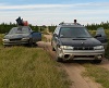
Mostly unrelated but B and I stopped by C's shop. Standard EJ25 with a rod sticking out. Has another one with rod knock, in his dreams he will eventually make one good engine out of two. The main reason we were there was to remove and disassemble a CVT out of a 2014 Outback. C bought the car pretty cheap knowing the transmission was bad and since he's cheap he wants to try to fix the trans rather than just replacing it. It still ran and drove but made horrible noises. Car has 208k miles on it but has minimal rust. Previous owner supposedly pulled his 18' pontoon boat in and out of the water with it regularly, which may not have been a good idea. Once we removed all the bellhousing bolts, the transmission wasn't too hard to remove. We first tried unbolting the front/bellhousing from the trans but that didn't seem to work. Then we unbolted the top cover and removed this valve body which also didn't accomplish much. Figured it was a long shot but removed this front cover and oil pump, also no real progress. These screws are pretty crazy though. Took the tailhousing off, standard Subaru auto trans clutch pack for the rear drive. Didn't really look at it at the time but seems feasible that some kind of planetary low range might be possible. Took the pan and filter off and some kind of splash/windage tray. Then we were able to split the case. Transmission is pretty simple really. Sheaves still look very smooth. Some burs/wear on the top edge of the pulley on the left, I'm guessing that's what was causing the intermittent nails on the chalkboard noise C told us about. Pretty sure we found the root of the problem. This used to be spherical. C plans on replacing that bearing, a sensor we broke during disassembly, and putting it back in the car.
-
B and I finished the remaining fab and paint on the skidplates and bumpers. Round tube bumper is for the rear of B's Forester, everything else is for my Impreza. Dropped it all off at paint today. Didn't listen to slammo and travelvw and asked the paint shop to match the gold color on the bottom part of the body for the front bumper and skidplate. Everything else will be black.
-
Most of the wiring and modules we removed. Keyless entry, airbags, TCU, ECU, aftermarket cruise wiring. At first we couldn't remove the ignition key from the lock cylinder even in the off position. If you plug the shifter (big white thing) in to that white wire plug and have it in park, then you can remove the key. Those blue and red wires go the park position sensor. The two black wires below that go to the lock cylinder seem to be the culprit. If you unplug them at this connector under the steering column you can take the key out normally. Then you don't have to deal with the park position sensor. The black connector with two white wires is the other side of the connector. Alternator wiring. The two big white wires go to the large post. Then the black/white wire is the same on both cars so I spliced those. Spliced the other one. I did order a wire plug for this so I can get rid of the splices. Spliced a wire off the EZ36 coolant temp sensor to the dash but that caused the Haltech and dash to read low. Thought about running an output from the Haltech to the temp gauge, maybe I will eventually but I installed an EZ30 coolant temp sensor. Same threads, has three pins instead of two. In the EZ30(D) cars, one pin (2) goes to the ECU, the other one goes to the gauge. I was hoping this would make the sensor read more accurately on the Haltech (I think it reads about 20F higher than actual) since that's what the base map was set up for but it seems to read the same as the 2 pin sensor. I ran this purple wire from pin 3 under the intake in some small loom. Put a spade connection near the engine harness plug. Unfortunately this didn't accomplish much. Seems to read the same as the EZ36 sensor on the Haltech. Gauge fairly quickly goes beyond H as soon as the engine starts warming up. For reference, the 2001 EZ30(D) sensor reads: 4.6kohms 30F 2.7kohms 60F 190 ohms 212F (not sure how accurate this is) The 98 Impreza gauge reads: 100 ohms (to ground) H 120 ohms 2/3 150 ohms top of C 180 ohms bottom of C So I spliced a 50 ohm(?) resistor between the gauge and sensor and now the gauge comes up more slowly, hits about 2/3 at 150F (on Haltech) and is then still reads above H at operating temp (200-210F on the Haltech). So I'll probably try a 100 ohm inline next. Here we have the wires for the instrument cluster. connector a/i10 pin 8 R/W check engine light (from Haltech) pin 9 G/W oil pressure switch (from engine) pin 10 G tachometer (from Haltech) connector c/i11 pin 3 Y/G auto trans oil temp (spliced to EZ36 oil level switch, see below) pin 11 W/G coolant temperature (need to figure this out, see above)
-
B finished welding the rear brumper yesterday. We also finally got the EZ36 running in the Impreza. Seemed to be running on all six, the only leak we noticed was one of the injectors so I should get new o rings for those. Cranked it for a while to get some oil circulation and maybe pressure. Even without the fuel pump running it started to fire when we plugged in the ECU. Fired right up with some fuel pressure, responds to throttle pedal. Only ran it for 5-10 seconds a few times. Still needs a lot of little things but a bit of a relief to hear it run. I'm going to try to put all the details of the engine swap on this thread: Will probably start copying some of the relevant info from this thread into there and use this thread for our usual fabrication, repairs, and trip reports. Thought it might be handy for future reference to have all the engine swap info in one place.
-
Download the FSM from jdmfsm.info, most of the following is from that. Pinned out connector to EZ36 Some Impreza specific wiring: Was looking for a good source of 12VDC with the ignition on that's not shared by any other fuses. Since we removed the airbags, computer, and wiring, it was convenient to tap into the airbag harness connector near the dead pedal. Ran the pink wire from pin 13 of the Haltech to that. Pin 6 connector B31 red wire as seen below: Almost spliced into the B/R wire running to the fuel pump by the passenger footwell but decided to tap into the connector that normally goes to the fuel pump relay (white thing on the left side of the picture). Ran the orange/blue wire from the Haltech fuse box there. Pin 4 of B46 black/red wire as shown below: Also wanted a dedicated but fused battery voltage source so tapped into the ABS connector since that will no longer be functional. Goes through the main 80A fuse and a 50A fuse in the main fuse box and then over to the ABS module (W/R wire marked B). Plugged the red, red/white, and red/green wires for the Haltech fuse box in to that. Used a large ground wire there too (black wire marked G), ran the black ground wire from pins 10 and 11 of the Haltech to that. Pins 23 (black) and 25 (white/red) of F49 as seen below: Simplest way I could figure to do the starter circuit was to splice these two wires (large W/R and W/B) that originally went to the shifter on the auto trans. Cut them on the large side of the factory splices and spliced them together. Large white/red and white/black wires of B12 as shown below: For some reason we had to unplug the stock ECU for this all to work properly but we were obviously going to do that regardless. I plan on adding more detail to the above and other wiring as I have time.
-
As noted above this is for an STI accelerator pedal, I think the pinouts on the Legacy/Outback and possibly the one shown on the Haltech site are different so definitely verify that. Most of that was figured out from the basemap I got, Haltech's site and instructions (their color coded wiring diagrams are great) and the FSMs. One minor hurdle we had was the Haltech EZ30 basemap being set up for a PWM pump (I think), had to switch that to the B/Y wire so it would actually turn on the fuel pump. Fuel pump seems to run continuously with ignition on even if the engine isn't running, haven't looked to see if or how that can be changed yet. Also had to adjust the pot position on the accelerator pedal to keep from getting an error at full throttle. Simple, just two phillips screws. Also have to calibrate the accelerator pedal and DBW throttle, also simple, just follow prompts on the screen.
-
Going the other way, wire colors to the ECU connector for reference. 2013 EZ36 pinout color (car) B21 54 pin color (engine side) GY/L 1 Lg knock sensor 2 (signal) GY 2 GR intake cam pos sensor RH (signal?) Y 3 W crank position sensor Also 14 GY/G 4 LR knock sensor 1 (signal) G 5 Lg intake&exhaust cam pos sensor LH&RH (ground?) B/W 6 YG throttle control, MAP, coolant & oil temp sensor, knock sensor 1&2 (ground) IGN GY/R 7 L exhaust oil flow control solenoid valve RH 8 B Or EGR control solenoid valve Y/B 9 RY ignition coil 1 Y/G 10 WL ignition coil 4 11 RG purge control solenoid valve (signal?) gauge V 12 BrW coolant temp sensor (signal) Y 13 G intake cam pos sensor LH (signal?) G 14 B crank position sensor Also 3 GY/BR 15 BY exhaust cam pos sensor RH (signal?) 16 W oil level switch switched to ground G/R 17 L Or exhaust oil flow control solenoid valve RH 18 PB power steering oil pressure switch switched to ground 19 BL EGR control solenoid valve Y/R 20 YG ignition coil 2 IGN GY/R 21 L intake oil flow control solenoid valve RH G 22 R intake oil flow control solenoid valve RH Y 23 YB MAP (signal?) O/R 24 Or throttle control signal? O/B 25 W throttle control signal? GY/B 26 G exhaust cam pos sensor LH (signal?) gauge 27 L engine oil temp sensor (signal) O 28 LY throttle control, MAP (power?) 29 YR EGR control solenoid valve 30 Y EGR control solenoid valve Y/O 31 GW ignition coil 3 IGN GY/R 32 GY intake oil flow control solenoid valve LH G/B 33 RY intake oil flow control solenoid valve LH B/W 34 BP ground for ECU? B/W 35 LR ground for ECU? B/W 36 WR ground for ECU? (coil ground?) B/W 37 LR ground for ECU? BR/R 38 BW throttle control BR/B 39 BL throttle control B/W 40 BP ground for ECU? 41 IGN GY/R 42 R exhaust oil flow control solenoid valve LH G/BR 43 RW exhaust oil flow control solenoid valve LH Y/L 44 BY ignition coil 6 gauge cluster 45 G Or oil pressure switch switched to ground L/Y 46 GW fuel injector 6 L/O 47 Br fuel injector 5 R/L HTFB 48 YL intake&exhaust cam pos sensor LH&RH, fuel injectors 1-6, purge control solenoid valve (power?) R/Y HTFB 49 LB ignition coil 1-6 (power – ignition relay?) Y/BR 50 BL ignition coil 5 L/R 51 RG fuel injector 4 L/BR 52 G Or fuel injector 3 L/B 53 LR fuel injector 2 L 54 Lg fuel injector 1 HTFB = Haltech fusebox STI accelerator pedal pinout (left to right looking at harness connector) O 1 sub 5V+ O/G 2 sub signal (analog) O 3 main 5V+ B/W 4 main ground O/Y 5 main signal (analog) B/W 6 sub ground
-
I used the Haltech fusebox kit which has four fuses and relays for ECU, injectors, ignition, and fuel pump. Chart of wires from the Haltech and which pins on the engine connector and throttle pedal I ran them to. Main connector 34 pin (Elite 2500) looking into connector on ECU 1-9 left to right top row EZ36 ECU Haltech Wire Colour Connection EVAP 1 V/BR DPO 2 Pedal 5 2 O/Y AVI 4 9 3 Y/B IGN 1 20 4 Y/R IGN 2 31 5 Y/O IGN 3 10 6 Y/G IGN 4 50 7 Y/BR IGN 5 44 8 Y/L IGN 6 28, pedal 1&3 9 O +5V DC GND 10 B BATTERY GROUND GND 11 B BATTERY GROUND - 12 O/W +8V DC IGN 13 P 12V IGNITION INPUT AC request 14 W AVI 10 ( TPS ) 23 15 Y AVI 9 ( MAP ) 25 16 O/B AVI 2 24 17 O/R AVI 3 tach 18 V/B DPO 1 54 19 L INJ 1 53 20 L/B INJ 2 52 21 L/BR INJ 3 51 22 L/R INJ 4 AC clutch relay 23 V/R DPO 3 Haltech relays 24 B/Y DPO 5 ( FUEL PUMP TRIGGER) Haltech relays 25 B/R DPO 6 ( ECR OUT) Haltech relays 26 R/L ECU INJECTOR POWER INPUT (REQUIRED CONNECTION FOR ECU TO OPERATE) 47 27 L/O INJ 5 46 28 L/Y INJ 6 29 L/G INJ 7 30 L/V INJ 8 IN2 22 31 G STEPPER 1 P1 / DPO IN1 (LH) 33 32 G/B STEPPER 1 P2 / DPO EX1 43 33 G/BR STEPPER 1 P3 / DPO EX2 17 34 G/R STEPPER 1 P4 / DPO Main connector 26 pin (Elite 2500) looking into connector on ECU 1-7 left to right top row EZ36 ECU Haltech Wire Colour Connection 3 1 Y (SHD) CRANK (TRIGGER) ( + ) Inangle1 (LH) 13 2 Y (SHD) CAM (HOME) ( + ) 3 GY AVI 7 (AIR TEMP) 12 4 V AVI 8 (COOLANT TEMP) 14 5 G (SHD) CRANK (TRIGGER) ( - ) 5 6 G (SHD) CAM (HOME) ( - ) 7 GY/R (SHD) SPI 4 Inangle2 2 8 GY (SHD) SPI 1 Exangle1 26 9 GY/B (SHD) SPI 2 Exangle2 15 10 GY/BR (SHD) SPI 3 IGN 11 R/W +13.8V ECU SUPPLY (ECU POWER) 12 GY/O (SHD) AVI 6 (O2 INPUT 1) 13 GY/Y (SHD) AVI 1 (O2 INPUT 2 ) 6,34,35,36,37,40 14 B/W SIGNAL GROUND Pedal 4 15 B/W SIGNAL GROUND Pedal 6 16 B/W SIGNAL GROUND CEL 17 Y/V IGN 7 18 Y/GY IGN 8 FAN relay 19 V/O DPO 4 Pedal 2 20 O/G AVI 5 4 21 GY/G KNOCK 1 1 22 GY/L KNOCK 2 CAN O2 23 W CAN H CAN O2 24 L CAN L 39 25 BR/B DBW 1 / DPO 38 26 BR/R DBW 2 / DPO
