


Rampage
-
Posts
682 -
Joined
-
Last visited
-
Days Won
25
Content Type
Profiles
Forums
Gallery
Store
Everything posted by Rampage
-
I just found this. After battery replacement... Electronic throttle system Turn the ignition switch to ON, wait for 10 seconds or more, and start the engine. Engine control system Let the engine run at idle until it fully warms up (the radiator fan turns 2 times or more) under no electrical load condition.
-
Like 1 Lucky Texan said, with a dead battery the computer system has to relearn certain things. The steps to take (battery replacement) should be in the owners manual. The security system is designed to keep the engine from cranking. The fuel pump relay is controlled by the ECU, so maybe it is not keeping it running or making the proper air fuel ratio because the relearn process is not complete.
-
Same thing happened to me once with my 68 F100. 3/4 tank of water. I ran it on lighter fluid to get back to the gas station. Since it starts and runs with starting fluid, the crank sensor is working. I would get 1 or 2 bottles of the highest percentage of rubbing alcohol you can find like 90% and dump it in the gas tank. Cycle the the pump with the key a bunch of times, then try to start it. You can try Dry Gas, but I don't think the percentage is that high. The alcohol will mix with the water and make it somewhat burnable. Of course it depends on how much water is still in the system. I see the fuel filter is the top part of the fuel pump assembly. The alcohol will displace the water in it and the fuel lines.
-
On the engine side of Connector B21----for the 07 model- PIN 4 is used on the Turbo model and STI. The wire color is Lavender/Red stripe. The Non Turbo uses PIN 10. The wire color is Black/Lavender stripe. I don't know why the different pins. You said the color wire on Pin 4 is a Pale Yellow. Count in from the other side of the connector and what color is it? The body side of the connector Pin 4 should be Lavender/Red stripe. That will be the pin to use. If you are not sure which one to use, I would disconnect the battery and check continuity to the ECU connector (A30) - Pin 30 on B134. The wire color there is Lavender/Red stripe on all three models. Usually looking at the wire side of a connector the pin numbers are backwards. The picture shows the pin side of the connector. On the body side of Connector B21 the 09 uses Pin 4 Lavender/Red stripe. For a test, I would poke a straight pin into the connector along side the wire, or lengthwise into the wire itself and wrap and tape a wire to it and run it to ground. Then if that works cut and splice the grounded wire onto it.
-
The diagram you posted for 09 is for the TURBO model. The 07 and 09 NON-TURBO are like the 07 you posted.
-
Sure hope that fixes it. Wait and see. If it acts up again here is one more thing to check. Voltage on fuse 11 or 14 with Key ON and when cranking. That is the voltage out of the IGN SW when ON and Cranking.
-
That really is a weird problem. Here are a couple thoughts. When cranking, something is starving for power until you connect the jump pack. That will supply extra current and keep the voltage up when cranking with the starter. Once it is running the ALT outputs over 14 volts so the amperage is up and it keeps running. Maybe it wants a higher amperage battery. What does the voltage drop to when cranking. And what is the drop with the jump pack connected? The starter motor could be drawing more current than normal. After all, it is an electric motor. My first thought was battery negative grounds to the body. Add a few and see what happens. The ECU gets several grounds off the body. Fuel or spark would be next. When it doesn't fire check for spark from the coil. And see if the fuel pump is running while cranking. Or, better check the fuel pressure with a gauge.
-
In the picture you posted, the large Connector B21 Pin 10 should be a Pink wire on the engine side of the plug. On the vehicle side it is Yellow/red going to the ECU. Is there a Pink wire on Pin 10 or is it empty? And is there a Yellow/red on the other half going into the cabin? On the connector you highlighted E61 Pin 2 goes to (A30) B134 Pin 30 and E61 Pin 1 goes to ground. You will see that on the next page following the W. On this page the W is on the right side, on the next page it will be on the left.
-
Same thing happened to our 95. My wife called and said she could not hear the fuel pump run. I grabbed another pump and we swapped cars. There was voltage at the plug so I pulled the pump assy. and found the burned connector underneath. I hooked two wires to the pump, brought them out under the rubber gasket and remounted the pump assy. I hooked the two wires to the wires going to the US Mail roof light and drove it home. Then swapped the assy.
-
Check out this VIDEO from scannerdanner.com on how to check the coil and Igniter with a test light and volt meter and a scope for input and output pluses. Scroll down the page and look at the drawing of how it is wired. If there are no pulses into the Igniter on one of the wires, you will have to trace it back to the ECU.
-
When you remove the panel under the steering wheel, look for two green connectors (test connectors). Plug them in to each other and turn the Key to ON, no start. You should hear the fuel pump cycle on and off along with relays, solenoids and the radiator fans. The cycle will repeat until you turn the key off. If you don't hear the pump run check the connector at the pump for voltage. On that connector there will be two wires that should be hot. The small one is for the fuel gauge. The larger one is for the pump. Don't forget to unplug the test connectors.
-
That is it. Upper left corner in photo. The ECU sends signals to it and it controls the coil. There are two power transistors inside of it that act like high speed switches. One transistor controls the front coil in the coil pack (cyl 1 and 2) and the other one controls the rear coil (cyl 3 and 4). They seldom go bad, but 95% chance it is your problem.
-
You can get single sections of the FSM as pdf files at the following link. Left Click on a folder to open it and Parent Directory to go back. Right Click on a pdf file and Left Click on Save Link As or Save File As. Then select or make a folder to save it in. The Wiring Diagram you want will be the largest file size. The Harness is usually near the end of it. Index of /Auto/Japan (jdmfsm.info) If you go to the following site, you can download the entire FSM in Zip format. Subaru Factory Service Manuals (FSM) - Every Model - USDM/EU (sl-i.net) Click on the one you want in the chart and a new page will open. When you click on the download button (name of the file upper right) on the second page if a new window opens, close it, it is an add. In File Explorer, Right Click on the saved zip file and left click on Extract All. It will extract it to a folder with the same name as the file. BTW, I have file explorer options set to show file name extensions. Makes it easier to identify file types.
-
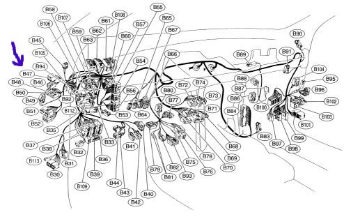
Yep... It is on the drivers side, under the dash, all the way at the top above all those wiring harnesses almost in the front corner. The fuel pump relay is usually the round body one and snaps into a spring loaded U- shaped clip. You can pry it out of the clip and pull it down a little and unplug it. Not easy to get to. Remove the cover panel under the steering wheel. Put your hand against the outer edge of the firewall and go up as far as you can and feel for the round one. Connector B46 green in the photo of the harness. B47 brown is the main relay.
-
You said you replaced the coil pack. Is it mounted on top of the intake?
-
Sorry, wrong engine.
-
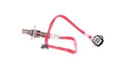
I used to work at a large auto parts store and have seen the same thing multiple times. No part listed. Even with paper catalogs. I looked at the Bosch catalog and it only lists the SOHC 1.5 and the years 2000 - 2007 are blank for the upstream sensor. The part numbers 22641AA381, 2641AA480 and 22641AA400 does not exist on the US Subaru sites I looked at. I did not check all of them. Using Google I found 22641AA400 is a good number for the 1.5 (in stock at some places) and it looks like your sensor.
-
Looking at the catalog you posted, and a picture of that sensor, I would say yes, the DOX-0361 will fit. It has the 6 pole connector with 4 wires. And, in your picture it looks like there is a flange under the hex.
-
Your 15W40 should be good, don't change, unless you go to 20W50 in the summer. If you want to learn how to swear, change the hose that goes to the block, underneath the plastic Y that the PVC hose connects to. I hate that one, it usually comes off in pieces. If it is not oily around it, leave it. Back in the mid to late 70's I read an article in some racing magazine that there was a company that tested every Racing Oil on the market with 5 different tests. The only one that did not break down was Valvoline 20W50 Racing Oil. They developed two more test before it started to break down. I had been using it before I read that. I'm sure there are copycats now.
-
This one. Part# 10001. Substitute one quart of oil when changing oil and filter. I also use 10W30 regular or a synthetic blend oil. Never full synthetic in a high mileage engine. Good thing @idosubaru mentioned PCV valve. I change them when doing other stuff on the engine. And the molded rubber hose that connects to it gets hard and will crack.
-
When connecting those plugs listen for the click when it latches. It has to compress a rubber seal on the inside. With the engine running use needle nose pliers and wiggle and pull on each wire of both connectors both sides and see if the engine stalls.
-
Makes you feel great huh. All that tension gone. That is really not that bad for an old engine. What oil do you use in it? The next time it is down a quart put in a quart of Lucas Motor oil treatment. I use it in our 95 and 97 EJ22's.
-
Thanks. What really helped was that last picture with the wire nut. Made me think the PO bypassed the ign. relay, which he did. I have wired many vehicles from scratch over the years mostly old ones. The ones I liked doing for friends are a GTO from the drag strip back to the street, a 37 PT50 and a 52 Ford pickup. Sometime this year I will wire a 32 Ford pickup, 460 w/blower and 2 4's for the street.
-
I wish I could get my hands on it to sort it out. It looks like he used a red wire nut to connect all those wires together. Remove the tape and unscrew wire nut. Put it back on the Black (hot) wire OR pull the 30 amp fuse. To play it safe check for voltage on the removed wires. They should all be dead. Check for continuity from each of the wires (probably Red/Y) to pins 2 and 13. Mark the one for pins 2 and 13. Scroll up and look at the wiring diagram you posted. The wires from the fuse to the relay are Yellow. The wires out of the relay are Yellow/Red. If the continuity check says one of those wires goes to pins 2 and 13 it must be moved to the output of the relay, or add another relay to power it. With the fuse in I would check amperage draw on each of those wires one at a time from the black wire with an amp meter.
-
The injectors will always be hot from the 30 amp fuse. If the voltage goes away from B48 pins 2 and 13 when you pull the 30 amp fuse, but not when you pull the relay, then it sounds like they are wired to the fuse output wire instead of the relay contacts. If the diode is open the ignition relay will not operate. With the Key ON, Fuse 16 supplies voltage through the diode to the coil in the ignition relay and the other end of the coil is grounded, so it will close the contacts. If the diode is shorted the relay will still work.

