Rampage
-
Posts
682 -
Joined
-
Last visited
-
Days Won
25
Content Type
Profiles
Forums
Gallery
Store
Everything posted by Rampage
-
The thing about using standard rings is both the rings and cylinder wall will wear giving a good seat. Chrome rings, different story. Check the ridge at the top of the cylinder. On other (non-Subaru) engines I have worked on I always used a ridge reamer to remove the ridge at the top of the cylinder to prevent cracking the new compression ring if it hits the ridge especially when using different pistons.
-
With the inner and outer bearings being so close together they have to be rollers because of the pressure on them when turning the wheel. Ball bearings last. We have a 95 and 97 Right Hand Drive Legacy wagons that used to deliver US Mail every day. They are now retired since my wife retired from the postal service. If I could not get Subaru wheel bearings I had good luck with NAPA bearings. Other aftermarket bearings would only last 3 days to 3 months on the mail route.
-
Start it up earlier in the morning.
-
It is nice that it is working.......but...now what do we look at? Electronics is a possibility and could be random. Electronic circuits work best when cold, but connectors and solder joints do not. Letting the engine warm up before trying the heater could be the secret. Hot coolant flowing through the heater core would warm up the box it is in and help the (electric) door actuators to work.
-
You're welcome. I have the 1990 legacy parts manual pdf. Took a little while to find them. You can download and save it HERE. Click Parent Directory to go back.
-
If this is a sedan, open the trunk and look under the rear deck (rear window) for a two pin plug that goes to the high mount brake light. You can wire into that.
-
I think the only difference is With or Without ABS. Go HERE and look up the Legacy Wagon or Outback and you will see other models and years are the same except for ABS About the two bolts that fasten the knuckle to the strut. One is just a bolt. The other is for adjustment. I use a chisel and make a small mark on the washer part of the bolt head and the strut so I can put it back in at the same spot. Do that on both cars in the same area, like straight out from the center of the bolt. Keep the bolt with the knuckle when you install it. You should get a wheel alignment afterwards to be safe.
-
These should be what you want. 3 of them. O-ring Fuel Pipe. Item # 9 in the picture. Subaru LINK
-
No problem, I do the same thing sometimes, skip a word then have to read it again. We need to know if coolant is flowing through those two hoses and the heater core.
-
We were asking about the heater core hoses that go through the firewall to the heater core. One or both, cold, warm or hot after a few minutes of idling? With the temp gauge at normal, both of those hoses should be hot. When you said bottom hose, I think of radiator hoses.
-
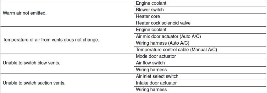
As Numbchux said, if both heater hoses get hot then the problem lies with the door actuators in the heater box or the unit that controls them. Probably the Air Mix door actuator. I've replaced a few of them on different vehicles. Sometimes called blend door actuator. In sub-zero weather the lower radiator hose might get a little warm, but will not get hot unless you have cardboard in front of the radiator.
-
Had that happen to an aftermarket radiator in our 95 RHD Legacy. The OE started loosing the fins between the tubes at the bottom of the radiator.
-
Those two holes are there for you to tap threads into them and use a puller to remove the sprocket.
-
Looking at the FSM wiring diagram - The B21 (20 pin) connector carries the crank and cam sensor signals to the ECM. The ECM will not trigger the injectors without those signals. The B22 (16 pin) connector carries the 12v and ECM signals to the injectors.
-
Yes, plugged in. If you unplug it, then you must use battery positive for the test light to test the wire from the ECM like in my last post. If you have a sewing kit look for straight pins that have a plastic ball on the end or shaped like the letter T. You can push them in along side the wire into the connector. The wire has a rubber doughnut around it to seal it in the connector.
-
If you have battery voltage on one of each injector pins while cranking, the main relay is probably ok. Battery voltage drops when cranking. One pin of each injector is supplied 12v and the other pin of each injector is switched to ground by the ECM to open the injector. Maybe the ECM is loosing its external ground connections to the body and cannot switch the injector to a complete ground. Not letting fuel through the injector. That would explain the engine starting with one injector unplugged. Less load to control. I do not know where all the ground wires are located for the ECM on the body, but you should try to find them and check them for corrosion and rust. When testing an injector plugged in with a test light, you ground the test light wire and touch the probe on the 12v supply pin. The light should stay on while cranking. Move the probe to the other pin and the light should be on and flicker when cranking. Or, you can move the test light wire to battery positive and check that pin. The light will be off and flicker on when cranking.
-
I've never driven anything that fancy and probably never will. I can see cameras having a problem with reflected light on wet roads. Found this on a Subaru site. - the EyeSight camera lens (it’s set of eyes) is located at the top of the windshield.
-
Good video. Notice that all the pullies have dual bearings instead of one in the center. You can paste the link as text.. Or like this using the link button in the upper tool bar. First, highlight and copy the URL link. Then highlight the text in your post (Chevy 454 snow blower) (can be one or more words) then click the link button. A window will open. Right click in the URL field and Paste your link. You will notice the word or words you highlighted are in the next field. Click Insert into post. It will look like the following. Chevy 454 snow blower. I sure could use one of these right now.
-
Cool, it ran with an external injector plugged in. That is what I wanted to hear. It sounds like the #4 injector coil has some shorted turns or is shorted to the housing of the injector. If you have an OHM meter, see if you get a reading between the two pins on #4 injector and the body of the injector. It should read open. No resistance at all even at a high setting. Measuring OHMS on the two pins only tells you half the story with a coil, unless the reading is very low compared with the other injectors. You could change the o - rings on the one that leaked externally with o - rings from the other old ones and replace #4 with it.
-
Try this for S&G. When you have the engine running on 1, 2 and 3, wiggle and twist a little bit the #4 connector. If it is still running plug one of the old injectors into the #4 injector connector. Does it die?
-
This is only a guess without a schematic of the ECU. Each fuel Injector should have one transistor to control it, so there would be 4 identical (Darlington) transistors (usually NPN type). The control chip sends a pulse to the Base of each transistor to turn it on (like a switch) and cause current flow from the Collector (+) to Emitter (-). The Emitters of the two transistors in the photo are grounded through a current limiting resistor. The big resistor that fried. The Collector of each transistor will connect through the socket to a wire going to its injector coil. The other pin of the injector coil connects to 12v. In the burned section is one of those transistors so there should be 3 more with the same part number. Again, I'm guessing, but the photo shows the common thing between two injectors would be the supply voltage and the grounding resistor for the two transistors. If you can, follow the traces from each transistor Collector (the center pin that sticks out from the other two) to the connector socket pin and see what color wire is on the plug. It will match the color on an injector plug. Also check the ground wires on the connector. You can see the two Emitters are connected together and go to the big resistor. The other end of that resistor might to to a pin on the plug for a ground. Different name for the same unit. ECU, ECM, MPFI, SPFI.
-
You have a 97 RHD forester. What is the 03? Is the 03 also turbo? If one is RHD and the other is LHD, you cannot just swap wiring harnesses under the dash. All the parts are on opposite sides under the dash. You would have to modify all of the harnesses to match the parts locations. If both are RHD. Check for part differences. Sometimes they move parts to different locations in different years, and the 03 may have parts the 97 does not have, or a newer version of some parts. Download both FSMs and look over the wiring diagrams for similarities or differences. Go to the Harness section and compare the engine harness, engine bulkhead harness, then the bulkhead in compartment harness (under dash).
-
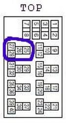
I can not find a JDM wiring diagram to look at. This info is from the USDM FSM wiring diagram that heartless posted. Look under the dash (drivers side) for the relay panel. Image below. I circled the DRL Relay. I don't think the relay is your problem. If you look at the headlight wiring (2 pages) it seems the DRL Module is not sensing that the headlight switch is turned OFF. Also, I cannot find an ambient light sensor for the DRL Module, but I did not look at every page.
-
Take a look at THIS site based in the UK. All JDM stuff. All the transmission numbers listed have the same gear ratio and final drive ratio. But it does not say anything about electronics. They put a lot of effort into making that site with all that info. The page will open with your transmission number. It shows the vehicles it was used in, 3 of them and the years. You can click on your model version or any of them to see more info. Then click the back arrow in your browser to go back. Scroll down the list to the VTD section and find the second number in your post. Click on it to view info on it. Then click on the vehicles listed. They do say turbo. One thing different that I noticed was this. TZ102YB3AA: Electro 4-Speed Automatic (E-4AT) TV1B4YB1AB: Electro 4-Speed Automatic (E-4AT) with Sportshift Maybe someone else will know if there is compatibility issue with that.
-
I had forgotten about the backup tapes and all the headaches. Then came zip drives with zip disks. (overgrown floppies) Some business's still use those.