


subaru1988
Members
-
Joined
-
Last visited
Everything posted by subaru1988
-
I got the timing squared away on my car, and it actually runs pretty nice. I can let it sit and idle for as long as I want now, as opposed to 30 seconds or so before it wanted to stall. The issue was TOO MUCH timing. I believe someone messed with my dizzy, and the timing was WAY off, and it was this way for years. I should have verified TDC with the cap post/rotor/flywheel marks years ago, but whatever. It used to ping pretty bad at part throttle up hills for years before I undertook this whole project, and I get NOTHING now @ 20 BTDC. It was nice to drive it again, the temp needle is just under 1/2 way up, and 2 TBSP of Subaru Coolant Conditioner seems to have helped my weeping water pump bolt, but now.. A noise has cropped up on the front of the engine. It "sounds" like a noisy bearing or something rubbing, but I'm not sure. At cold start, it's obvious it's there, but when the car warms up, it's still there but nowhere close to being as apparent. Windows rolled up, you can hardly hear it cold or warm. That said, after the time and effort into this car so far, I want it right. I've got about 70 miles or so on the car after all the work I did to it. I took off the drivebelts today, and I started it for 10 seconds or so to isolate the power steering pump, alternator, and water pump as NOT being the issue. The noise was still there. What are the chances one of my brand new tensioners is bad?! Has anybody had that happen? Any other common things to look for that could cause noises? Anybody have an idea what that washer/shim looking thing is on the back of the oil pump pulley? I'm wondering if that could even be the noise source.. Can a timing belt that needs to be retensioned cause that type of noise? FWIW, they seem to be looser cold and after I come back from a drive, they do tighten up a fair amount with the thumb test. I'm used to the car with the belt COVERS ON. How much noisier is it really with them OFF? Thank God I left the belt covers off while I'm doing the shakedown on this car
-
I'm not sure of the major differences between your year and others, but you can get A LOT of FSM's right here (yes, they are free): http://jdmfsm.info/Auto/Japan/Subaru/--Old Models--/
-
I'll do that. I'm positive the dizzy is installed right now. I'm beginning to wonder if someone before me messed with the dizzy and didn't take the time to set TDC/rotor/cap correctly. At least I know where I'm at with relation to doing TDC/rotor/cap right now. *Edit- For anyone that sees this thread in a search, if you follow the instructions in the video I posted using the Subaru FSM sprocket pics as the way to find TDC compression stroke to install the dizzy, that's the CORRECT way you position the dizzy to use the factory #1 plug wire. My car runs pretty nice now, it even idles OK, and I was able to set the timing. Hot tip- pics and vids of other setups are nice references, but not all cars act the same. I'll look for the thread you referenced. Thanks for the help!
-
I had a few minutes to beat my head against the wall again today, so I took the opportunity :p I reinstalled the dizzy again, lined up the rotor, the dimple on the gear, and the cap post on #1. All of these marks are dead in line with each other. At ZERO, the dizzy housing started off at the far end of the slot toward the hood, and I set it about where I tried to make a mark the first time. The one slot end essentially being at 0 makes sense to me, but who knows. What reason would there be for the timing setting to be ATDC. Anyway, the engine is at TDC compression stroke, and of course 0 on the IGNITION marks for physically installing the dizzy. The sprocket CAM marks are 45 from each other outward. It started great, high idle worked fine, it idled better at cold start than last time. It DROVE great and drives nice. The stalling at IDLE issue remains. When it warms up, it wants to stall on me at idle. I have a new cap, new rotor, and the plug wires measured about 4.5 Ohms for the short wires, and 7.5 for the long ones. I have to say there were times before the belts broke that I did have to stab the gas to keep an idle. It just wasn't quite as bad. It was like 30 seconds worth, and then it acted up. In addition, one time it was zero degrees out last year, and driving that car was like a bucking bronco- it was surging like crazy. When the weather warmed up, problem gone, at least until it sat at idle for more than 30 seconds. Now it won't idle that long. No CEL light is on, BTW. It starts right up cold or warm. Now that I've eliminated the timing belts and the distributor position out of the equation, I'll guess I have to find out where to head next with getting this car squared away..
-
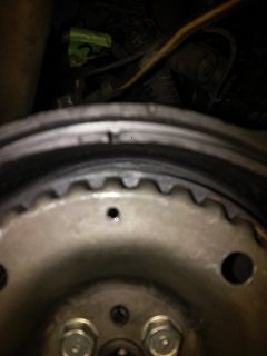
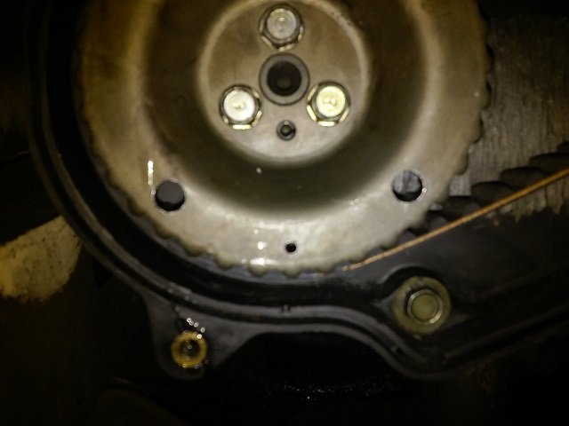
" I rolled it over like Miles says in the video to 12:00 on the D/S for the CAM timing mark, and then I kept going to ZERO on the IGNITION mark (sprocket timing marks at 45 degrees outward), and I put the dizzy in."
-
The pics above are from the 3 hashes for cam timing, right on the middle mark. The pic in this post is the flywheel position from those pics. That's the way it was when I installed it, and nothing has changed with any of that now. I check it every time I mess with the dizzy. If the cam timing was way off, I would think it would run rough all the time, if it ran at all. As I said, when it's actually driving, it runs alright. It's idling that's the issue. Just trying to find a better way than just stabbing in the dark at the proper alignment for ignition mark, rotor, and cap.
-
I hear you on the green connectors. What I meant in my earlier post was that I drove it, it stalled. I connected them to see if it would stay running so I'd have some idea where my timing was currently, it stalled. I couldn't take a reading. Same result either way. They're disconnected now until I can get it to idle to put the timing light on it. I did as you suggested in the other thread, and I have more of a feel for the gears. I'm just not good enough at it to determine one tooth or two teeth. That's why I'm trying to have some sort of reference point to know where I'm going. I'm trying to use the cap post #1, the gear dimple and bottom housing mark, and the hill holder spring. I'm certainly in that general area. After moving it yesterday, I'm more on the rotor pointing at the hill holder spring, that's for sure. Thanks..
-
Yes. Would it run decently at all if they were off? It idled last time I drove it, and they didn't change from then to now or from the pics below.. I check them every time because I wanted to be sure I was on TDC compression stroke like in Miles's vid. It is an EA82 1988 with SPFI. Same result either way. I drove it to warm it up, it wants to stall. Tried connecting the connectors to see if that would change it, it wants to stall. Last time before I changed it, it idled but I ran out of adjustment slot, and as you suggested in your replies, I was probably a tooth off then. It needs to be at 20, not 12, which is why I changed it. I have an emissions test coming up.
-
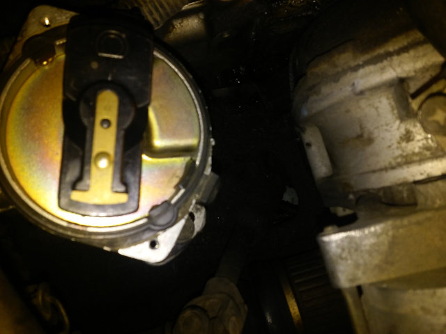
No . *Edit- After your post, I decided to try to see if I could get it lined up a little better at it's current 0 position on the flywheel, and it seems I did. The rotor is now much closer to pointing right at the center of #1 on the cap. This is all easy enough to change, but it's becoming an exercise in frustration for me when it seems like it really doesn't have to be. The car runs (drives) pretty nice, so the timing belt part of this whole project is over, or that's where I'd look first. I've already verified the marks and they're where they were when I finished that. The main thing I changed from the previous drive to today is the distributor position to gain more of the adjustment slot. I also tightened up a few plug wire to cap terminals. From what I understand, the reference point to find out if the "one tooth off" is the case is the #1 post on the distributor cap. The problem is, how much off is too much? I'm familiar with this procedure on old American cars, but this should be the same on the Subaru. Here's a vid I've been using to make sure I'm not going down some useless rabbit hole..
-
Here's to everybody having a better New Year than old year! Anyway, in a nutshell, did a timing belt job. I had to take the dizzy out. I couldn't mark the rotor location; the hold down bolts were marked with grime :). Timing belt marks are right on the tooth, the Driver side is a hair from being perfectly centered with the mark, Passenger side is right on. It actually runs (drives) pretty nice. I installed the dizzy, and drove it a week or so ago. I tried to adjust the timing. It DID idle that time, and all I could get is 10-12 BTDC, and I know it should be at 20 BTDC. I simply ran out of adjustment slot space. All indications were it was a tooth off. So I decided to "fix" it so I could get the 8 degrees I needed. Fast forward to today... I wanted to make SURE the gear mark was lined up to #1, as in the FSM, so I took it out of the car since I was going to move the rotor anyway, made sure my mark was right, and reinstalled it. The mark I made can be seen as a black mark on the lip of the dizzy housing in front of the rotor. I rolled it over like Miles says in the video to 12:00 on the D/S for the CAM timing mark, and then I kept going to ZERO on the IGNITION mark (sprocket timing marks at 45 degrees outward), and I put the dizzy in. The picture below is where the rotor was in relation to 0 on the flywheel, which is the suggested starting setting in the FSM. It's stalling at a stop on me. It doesn't run rough at all. After it's warmed up, and I go to check the timing, it just wants to stall while stopped. I tried a few different spots in between on the slot, same result. I tried to get the hill holder spring in the pic as a reference like the Fox video uses, but I couldn't. I've boiled this whole procedure down to 1) Mark on flywheel 2) Position of Rotor 3) Position of #1 on Cap. What do you guys think? Thanks!
-
Sounds like a plan..I'm going to make some reference marks, because the car does run decently where it's at. At least that's an OK starting point. I thought a little about this, and I'm thinking if I put the flywheel mark at 12, my rotor should be at or near #1 on the cap. This is easy to verify. So maybe I can move the rotor as you suggested while trying to get the rotor to point at #1 at 20 BTDC. I guess I'll know if I gain some slot length. I'm hoping I can get away with doing this without disconnecting the connector. I don't remember how much working room there is with it together, but I do recall the connector being a real PITA to get apart. As a matter of fact, it took longer for me to disconnect that than to take out the dizzy! Thanks!
-
Yea, I tried to get the rotor to line up with the mark I made when I had the distributor out. I lined up the gear mark as in the FSM, but I kept having to move the rotor around to try for the best spot I could get to install the distributor. I evidently went the wrong way or too far. It actually runs pretty nice at 12 BTDC. However, I know it will run even better if I put that extra 8 degrees in it. So if I turn the engine to 0 when I take the dizzy out (with the cam timing marks like in the FSM), when I put it back in, I need to move the rotor CCW to a point BEFORE where it's currently at 0, which is more or less pointed at #1 on the cap? Thanks!
-
So after all the really great advice I received in my long Timing Belt job (which seems to have gone OK) and water pump (which fought me, but it looks like I have the upper hand now ) thread, I'm doing some tuning on my RUNNING car. I thought I'd check to see if I'm on the right track here with a little timing issue. I had to take my dizzy out when I did my timing belts due to a SNAFU. I needed a new rotor to dizzy shaft holder screw, so I had no idea of where it pointed prior to taking it out. Anyway, I drove the car today, and frankly, it actually runs pretty nice, all things considered. It better with the amount of new parts on it. I went to check the timing after driving it a few miles and "warming it up". Warming up now is different than it was before with a new rad! Both hoses were hot, but I didn't hear the fan came on. However, I did see the needle drop at a certain point here and there, which I assume is from the fan coming on. So center of temp gauge, I then connected the green connectors, hooked up my timing light, and I had around 0 or TDC. I kind of expected that, because I installed it according to the FSM. Anyway, I'm out of slot length at 12 BTDC degrees or so. It does run better at 12; at 0 it was pretty flat on acceleration, which I understand. However, I know it needs to be at 20 BTDC. In addition, maybe the computer is "relearning" what it needs to also. So...I assume I need to restab the distributor. I know it rotates CCW, so do I turn it CW when I install it to gain lost range? I lined the rotor up the best I could before, but that was my first time doing this, so I was flying blind with it. My question is which way do you guys think I should turn the gear to compensate so I can get the full range of timing adjustment? Thanks for any insight!
-
I'm familiar with SBC's and that's the reason why all the RTV on the water pump threads gave me pause about maybe having holes that went into the coolant. I just chocked it up to the last guy going crazy with it like Idosubaru suggested, as pieces of it were hanging off the side of the pump. I also found pieces in the coolant when I drained it. The old school way of sealing SBC bolts, head bolts in particular, is Permatex #2, and that's why I'm familiar with it. If it can seal those bolts, it can surely seal a little M6 bolt. I thought about using some Bar's Leaks tablets, which I've had great success with in the past, but sometimes it takes time to work, and coolant leaking over belts is what put me in this mess in the first place. I'd like to get "right". Maybe I'm too paranoid about the belts now that I've gone through this whole process We''ll see what happens...*Edit- After a few very small turns of the bolts to creep up on a higher torque, I have it down to barely a seep, if that. That's good enough for me, so it's going back together. If it needs help, it's either a crushed up Bar's leak pellet which I have good luck with in the past, or the Subaru stuff. I'm hoping it will stay OK and not need any of that.
-
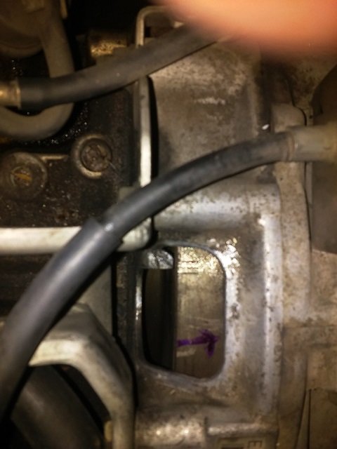
Yea, it sure is frustrating . I wondered why there was silicone on the threads. At the time I posted that, I had no clue whether those bolts went into the "water jacket" or what. It was on ALL the threads, so that's what I'm going to do too for purposes of tightening the bolts. I guess you put just enough sealer to fill the spaces between the threads. I'll go about halfway up since 75% of the bolt is in the water pump and not screwed into anything. I'm not sure what's going on with that hole. I can poke the back of the hole with a toothpick, but I can't feel anything. It does bottom out. I'm just going to treat it like it goes through. It's right next to the channel for the flow @ 11:00. Maybe it's the way I put the gasket on, I just don't know. I'm going to clean it all AGAIN, and go from there. Since I'm using sealant, I'm just going to reuse the gasket that I put on dry. I evidently bought the last new gasket in town, and that Aisin gasket frankly doesn't look bad at all. It wasn't even on there for 5 minutes. If it doesn't work, that's on me. It's not like I'm installing all the parts and taking them all off. I have a way I'm testing it, as I stated before. The pipe O-ring is the only thing that goes on and off, and I'm dunking that in coolant before installing, so hopefully it holds up. It doesn't leak.
-
I had a little time today to give it a shot, and the 11:00 bolt is leaking. I put sealer on the pump and the block side of the gasket, and I let it sit for 24+ hours. I plugged up the bypass and put the water pipe on, and I poured coolant into the pipe to get the pump full. When it was leaking, I pulled that bolt out, and it was almost as if the bolt DID go in the water jacket. It was WET with coolant and like a little stream coming out of the hole. This has me wondering if there is a flaw or some person (not me, as I stated WAY early in this, the threads & pump were loaded with RTV) overtightened that bolt and put a spot in that blind hold where coolant can enter. That hole, which leaked the last time, is right next to the water pump flow hole. The other explanation is that I somehow effed the gasket up, which after looking at it, I just don't see it. There was NO leak around the perimeter of the pump at all, and none at the 12:00 bolt this time. The other bolts were dry. That said, I'm going to get a few sacrificial bolts to line this gasket up with by acting as studs. 1) I'm using Permatex #2 as the gasket sealer; I've had good luck with it in the past. This time, I could try it on the threads. How much should I use on the threads? I've never had the need to seal threads before in a repair, and that includes an aluminum pump into an aluminum timing cover. Does it affect the bolt torque? 2)I had the original AISIN gasket on for less than 10 minutes with NO sealer. Is it possible to reuse it after it was wet with coolant if I coat it with a sealer? It's not damaged, it just got wet. It's dry now. I really don't think it should be necessary to buy a 5 pack of water pump gaskets. The Fel-Pro was oK, but of course coating it and waiting for the sealer to set destroyed it taking it off. I put the AISIN gasket on dry, torqued it down (too much, yes - up to 9lbs), saw the leak, and took it off. Would you use it? Sucks, but it's one bolt and figuring out how the coolant is getting into the hole. I know this whole project should have been over with weeks ago, but it is what it is. It's literally all that's keeping the car off the road..the timing belt job works fine
-
I had an M6X1.0 bolt from something else that had a bad head, so I cut the head off, threaded it in the short bolt hole, and I used my awl in the other hole to try to line it up. It still moved enough even with the sealer to feel resistance from the moved gasket hand threading the bolts until I propped the pump/gasket up a little to get the bolts more centered. It actually looks easy, but it wants to move around and that makes it tough. This was with the rad out and the grille off! To me, it's worth the extra 15 minutes to have a straight shot at it. It's 2 screws and 2 bolts. I'm letting the sealer set up to give it the best chance, so we'll see.
-
There's just a little corrosion on the block, but it seems more staining than anything else. MAYBE a few pits. Nothing obvious running my finger over it. The pump surface is nice. It's looks to be a nice quality water pump. I tried to keep the gasket in the right spot by using some small awls in two opposing holes. As I said, I used the gasket dry, so I had to have a way to keep the thing lined up as best I could. With a sealer, perhaps I can get it to stay in place better. I looked at my old gasket and I don't see anything obvious. When I put the new one on today, I did have to move it a little here and there to line up the holes, so I hope the sealer stayed even. I know some cars have aids to line it all up like nubs and studs....? *Edit- Last time, I put 9 foot pounds on them to see if going from 7 to 9 would help, and they torqued down OK. I just used my old bolts again because they should NOT touch the coolant. The bolts may have been a little overtorqued last attempt. As a matter of fact, I think the reason why the FSM doesn't state anything about the water pump bolt torque is that they expected you to use the "Torque Chart" for the engine and transmission. That says that an M6X1.0 bolt needs 4.3-5.1 foot pounds, so I did a little over 5 foot pounds and called it good. Maybe that's why my old pump's bolts seemed "loose" when I took it off. I guess if a bolt needed a different value, it would show it as it does the water pump pulley, etc. Good to hear it should be an easy fix. It's on, and I hope it all works. Thanks for the input, I appreciate it.
-
You're probably right about the RTV on the threads. From my understanding, if you have big pieces of it where it's not supposed to be, that may be too much. The way I see it is the gasket should be the barrier between the coolant and the threads, and it's not doing it..yet No helicoils or any thread repair from what I see, and I know 100% that a mechanic did the last water pump at 178K. It must have been an OK job for lasting 80K. Sad part is the timing belts were done at 177K. The next timing belt was at 232K with no water pump AND no tensioners done- just the belts. I have the receipts for most of it, and pretty much everything else starting at 10K, and it has 258K on it now. I'm done with the timing belt part of this "project". It starts right up and seems to run OK for the 10 seconds I ran it a few times. All it is now is cleaning it up again, getting a good seal on that water pump, and putting it back together after verifying that it doesn't leak. I don't want any coolant on that belt.
-
Whoa..That is bad. Guess there's hope for mine! I wasn't going to overtorque new bolts, I was maybe just going to try some new ones. I was thinking the threads might just be a little worn. However, as Step-a-Toe suggests below, it's really a joining issue, not a thread issue. You said earlier that the threads do NOT go through to the coolant, and I verified that myself when I cleaned out the bolt holes. I saw in the Haynes manual I have that M6 is 6 to 9 foot lbs of torque, so I gave 9 a shot, and it helped some but not enough. Next time with a thin coat of sealant on either side of a new gasket, I'll be back to 7.5 or so as you suggested earlier. I don't think 6 is enough torque for a water pump, and 9 didn't work, and trying more isn't worth the risk. You're right. The bolts don't go in to any coolant, so somewhere the coolant is getting to the bolts from around the gasket. I wondered why the garage that last did the water pump had RTV on the bolt threads, and now I know. Not so sure they had to use so much when others can simply use the dry gasket, so I'll try the happy medium with the sealer.
-
The 9 ft.lbs I wound up trying came from one of the EJ videos I watched. They were still 10mm bolts, yet they looked different in that they had a wider head. I'm glad to hear that you've worked on some beat blocks and still had them seal up. I know I can get it, it's just getting the right combo. The paper gasket should have worked, as you stated earlier, but time for plan B. Other than that, I would be driving the car as of yesterday with the timing belt job, new radiator (not exactly a drop in fit, FWIW!), and new water pump done. I think you're onto something with the whole RTV smearing deal. I guess it's the whole trying to compensate for the "if a little is good, more must be better" attitude. If I do use the gasket AND the sealer, I'll smear just enough on to cover the gasket on both sides and that's it. The sealer by itself, I guess a 1/8 bead is enough. Thanks for the input here and early on, it's must appreciated.
-
Good tip, thanks. I've seen some bad ones with water pumps for other cars. IMHO, the one I received with the Aisin pump was a "Subaru" gasket or at least the equivalent. It looks exactly like the OE gasket, right down to the color. Unfortunately, it didn't work right. I watched a few Subaru water pump videos on Youtube, and it made me wonder. The EJ? and other engines use 10mm water pump bolts, BUT they are flanged bolts from what it looks like. I'm not trying to reinvent the wheel here, but I'm wondering if new bolts are worth a try. Mine are OK, but the threads have a little wear here and there. Then again, as mentioned long ago in my thread, the bolts do NOT (well, should not) contact the coolant in any way. I did a search and I haven't seen anybody really say they've used just the RTV by itself with no gasket for water pumps. I know doing that seems out of the norm, but I can't be the only one who needs to compensate somehow for block "wear".
-
Thanks for the reply! I guess the Aisin instructions are for the best case scenario. I know about that Permatex water pump product, and I really debated about using it. I thought I'd defer to the actual instructions that came with the pump and on their "Aisin University" video, but that didn't work out so hot. I guess what I'll do is get a new Fel-Pro gasket and use the sealant together. I've always done well with Fel-Pro on other stuff. I know people say the OEM gasket is the best, but if I'm going to use sealant on it to make up for block imperfections, what's the difference. I can't get it right away, and frankly, I'm sick of waiting for parts to come in the mail. I can source the Fel-Pro locally.
-
So about those water pump bolts...heh . Now I know why there was sealant of some kind clogging up the threads. I have things back together (not the covers, thankfully yet), I know the car will run as it started right up, but.. I have seepage/leak from the 10:00 and 12:00 water pump bolts with the car just sitting after merely filling the rad. I torqued them all around 7.0-8 ft. lbs before adding coolant, and yes, I torqued them in a star pattern. I also cleaned the mating surfaces REALLY well. After adding coolant, and seeing the slight leak, I decided to give them a tad over 9 foot pounds (Haynes manual says 6-9 for M6 bolts). It improved a little, but they still slightly "leak", and I'm not torquing them anymore. I don't need that headache. The whole coolant + timing belts = snap is what put me here to begin with. This is why I decided not to install the front covers until I know for sure it's ok- just in case. I'm super glad I have that flywheel tool since it will make putting it all back together when it's right not so tough. Any suggestions for options to get these to seal up? I installed the paper gasket dry, as that is what Aisin specifically says to do. The gasket is a nice quality gasket, so I don't think it's that. I THINK I have a little pitting on the edge of the 12:00 bolt hole, but not the 10:00. Anybody use a straight RTV bead with NO gasket? I'll get a new Subaru gasket with/without a non-silicone sealer if necessary, but if I can substitute all of that with a gasket maker, that's fine too. Anybody done that? Thanks!
-
That $1 Allen screw I replaced the toasted original with was literally make it or break it...Believe me The positive part about taking the dizzy apart was finding a thread on here about the whole electronic guts/bearing of it being easily available for 1/4 of what a "new" dizzy would cost. I wish it wasn't dragging out, but man..Putting new parts with filthy parts would just be wasting my time. It takes longer to order stuff, but the cost savings is literally unbelievable. I'll take a length of time badge, too
