Geoff F
-
Posts
21 -
Joined
-
Last visited
-
Days Won
1
Content Type
Profiles
Forums
Gallery
Store
Everything posted by Geoff F
-
SOLVED! Thanks to everyone who helped me through this issue. I ended up splicing a wire into pin 10 on the vehicle side of the wiring harness and grounding it to a bolt on the engine. I checked continuity between this bolt and the negative terminal of the battery beforehand to ensure it was a good ground. I decided to splice into the vehicle side of the harness as opposed to putting a new pin on the engine side of the harness because I couldn't find a terminal/pin anywhere on the internet. The code was gone when I fired it up and its been running fine ever since. Cheers!
-
Just got done getting to the ECM. There are 4 connectors running into the ECM and B134 is the first from left to right. I matched the pins on the connector with the image of B134 in the FSM to be sure. Pin 30 on B134 is yellow/red and it actually runs to Pin 10 on B21 (car side of harness). I checked the continuity and bingo. Although this doesn't match the FSM with the sensor running to Pin 4 on B21, it does explain why there is a vacant Pin 10 on the engine side of the harness. For starters, I am going to put everything back together and simply ground a wire coming from pin 10 on the engine side of the harness. This way if I'm wrong then no harm will be done by cutting wires. If that works then I may go back to B134 and ground it there for aesthetic purposes, but I'm not too worried about that for now. Wish me luck!
-
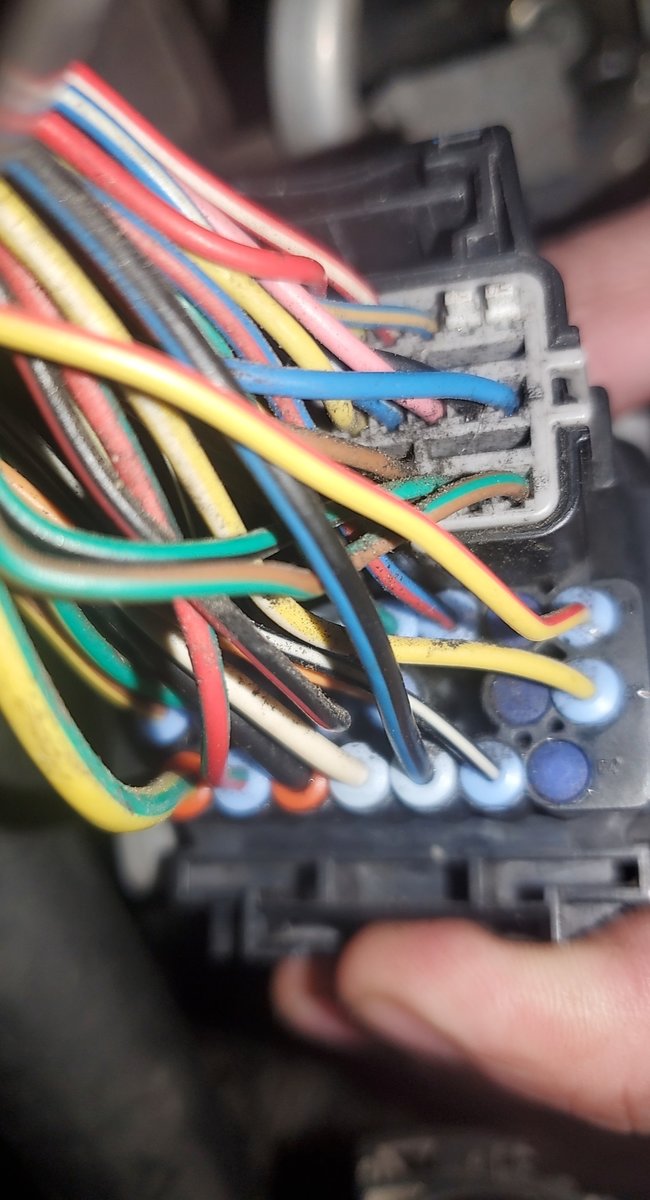
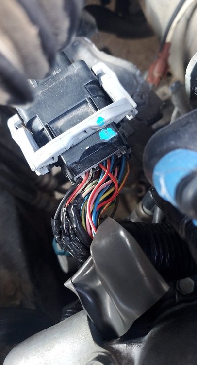
Sorry for double posting but the 2MB size limit on attachments is making me. Here is the engine side of connector B21 (JDM's work). If I look at it backwards like you mentioned I see that pin 4 is occupied by a red/pale yellow color wire. Could this be the red/lavender wire you were referring to and I'm just seeing it different?
-
Thank you for the detailed troubleshooting. This is the body side of connector B21 on my car...should be factory made and untampered with so this could be used as basecamp. Correct me if I'm wrong, but it appears that pin 4 is occupied with a brown/blue wire. And if I count from the other side then it looks to be a solid black wire?? Am I overlooking something or just colorblind?
-
Ah good catch! When I look at the two manuals the 07 has "EN(STI)" in the footer and the 09 has "EN(H4DOTC)" in its footer which proves you correct. That is some great news. Is there anything special I need to consider before going ahead with the job? My plan is to just cut the wire coming out of pin 4, splice a similar gauge wire into it, and ground it wherever. Thank you!!!
-
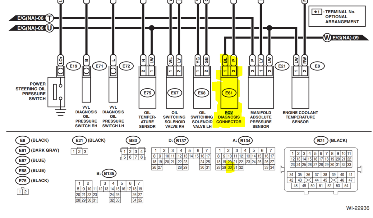
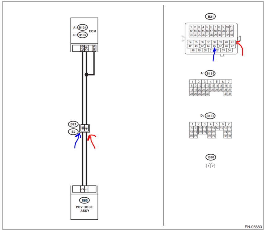
Let me take a step back as I now have a more clear wiring diagram for the PCV valve. However, it depends on the year of the car/engine. My car is a 2009 but the JDM motor appears to be from a 2007. I called JDM and the only thing they could tell me is to check under the oil fill cap for the year which indicates it is a 2007 motor (not very reliable, I know). So, the 07' manual shows (as GD mentioned) that the wire runs out of pin 4 and goes to a ground which would be very nice. The 09' manual shows the wires jump between pin 41 and 45. All of the previously mentioned pins are occupied on the engines wiring harness which makes me very hesitant to start cutting away without knowing what is what. Pin 4 is a pale yellow, pin 41 is yellow/red, and pin 45 is orange. My impatience tells me to assume its an 07' harness and to simply ground out the wire from pin 4 but logic is questioning how the only discrepancy between the two years is the PCV valve pin location. Wouldn't my car be throwing a ton of other codes assuming the pinouts are pretty different between years? I appreciate all of the help.
_LI.thumb.jpg.2b53e00a5a57541b47ed63c9263bc39e.jpg)
_LI.thumb.jpg.2a7e852e39c9ad6b89f50538525d4059.jpg)
-
This is an updated thread.
-
GD, Understood, but the sensor is not physically there (or at least the wires for it were cut and are hidden somewhere in the harness). If I had to make a jumper, it will have to come directly from the pins on the ECU so I have to figure out exactly where those two pins are. Thanks, Geoff
-
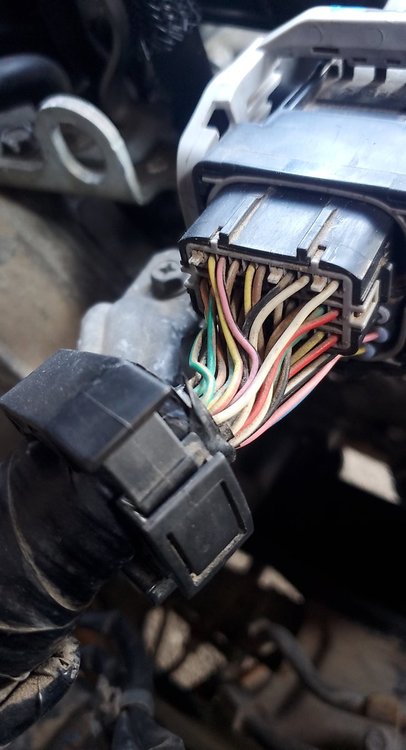
Hey all. Starting a new thread because it's been awhile since my last post about this topic. Long story short - I have a 2009 Subaru Impreza 2.5I that I did a JDM boxer engine (EJ253) swap with. Everything went smooth except I am getting a P1491 code (PCV sensor error). This is because the boxer engine I put in physically does not have the sensor itself and therefore the ECM from the car is not picking anything up on its end. So after some digging through the FSM I think I found the correct pins where I can put a resistor or jumper on the ECM to artificially complete the circuit and bypass the code. The only problem is that those pins are currently occupied and I am nervous that they may be running to something else. Could JDM just have capped the ends of these two wires somewhere in the harness or are they actually being used? Does anyone have any experience with this? I'm attaching some photos for reference. Picture 1: Wiring diagram found in the FSM. My plan is to put a resistor between pin 41 and pin 45 on B21 (wiring harness from the boxer engine) Picture 2: The back of the wiring harness from the boxer engine. Note that pin 41 is occupied by a yellow / red wire while pin 45 (hard to see) is occupied by a solid orange wire. Appreciate all the help and let me know if my logic is flawed! - Geoff

-
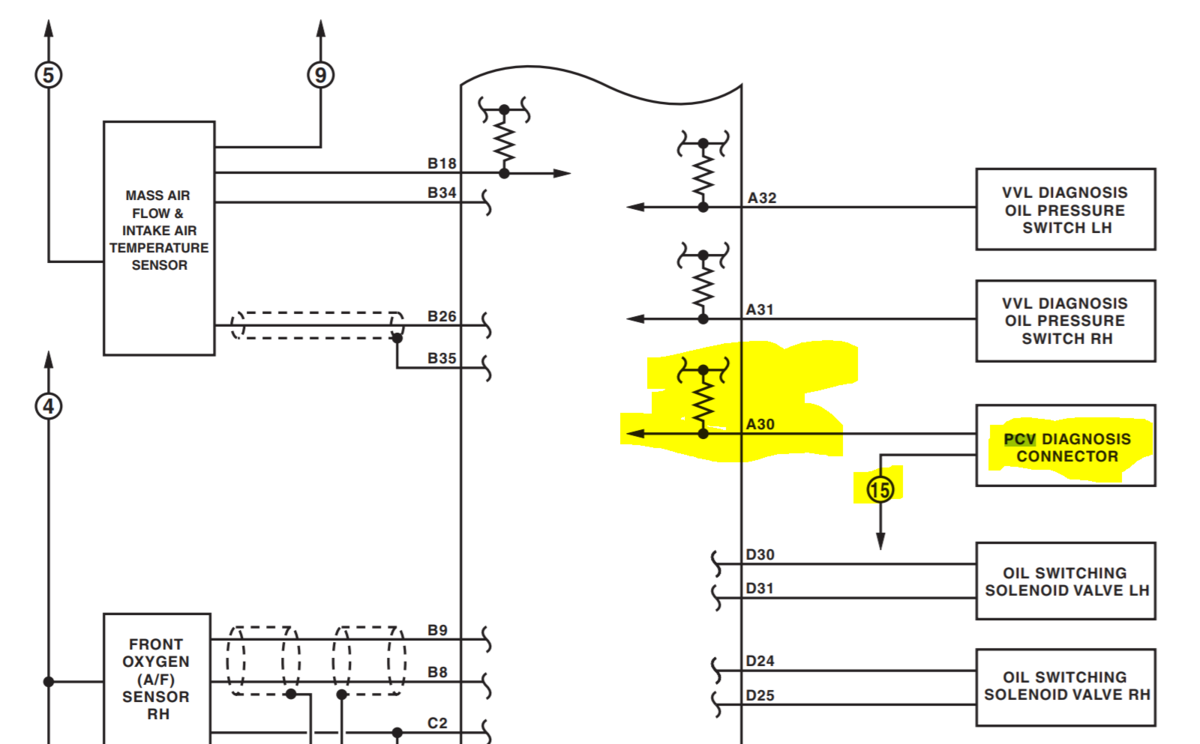
Thanks for the FSM Td! Sorry I'm so late to respond, kinda got lost on this project. I did not use the original intake manifold though, would have been a great idea. The only code I'm getting now is the P1491 code because the PCV sensor is not physically there, But I skimmed through the manual and found that the PCV sensor is connected to A30. Is this the pin on the ECM harness that it plugs into? I'm no electrical expert lol. I've attached some pictures of what I'm talking about. Thanks!


-
Hey all. I swapped engines in my 2009 Subaru Impreza 2.5I with a JDM boxer engine. After the swap I went through some of the codes (there are a few) and one that stuck out is P1491 which is a PCV function problem. The JDM motor I threw in didn't even have the sensor itself that connects somewhere on the intake so the ECU will never get a signal from the boxer engine wiring harness. I've read online that the sensor is essentially useless as it only checks for voltage making sure the thing is plugged in. Can I just rig up a little jumper cable between the two pins on the cars ECU so it completes the useless circuit? If so, does anyone have the pinout for the 09 Impreza 2.5I? The car is also throwing some ABS codes (0316, C0057. C0072) but I wanna take this one step at a time. Thanks!
-
Well folks, the verdict is out. I decided to take the engine out of the car and it is just as I suspected. After taking the exhaust manifold off during the removal process, I peaked my head up into the exhaust channels of cylinder one and sure enough all I saw were two cracked stems. Got the engine out and pulled off the head and there were the two heads of the valves just laying in the cylinder as if someone just placed them there. Two fresh carbon imprints on the piston head from where they collided but otherwise a completely undamaged head, cylinder, and piston head. My guess as to what happened is as I used the starter/breaker bar to remove the harmonic balancer bolt, the relatively loose timing belt (because of the failing tensioner bolt/thread) skipped a few cogs and smashed the piston head into the exhaust valves, snapping them perfectly in a split second. This must be the case because if it had happened at any other time I surely would have heard the valves getting mauled in the cylinder and they would be severley damaged. I had barely even turned the ignition when using the starter yet it was enough to do the damage. So, aside from the two exhaust valves on cylinder one, the engine is in complete working order. Any recommendations as to where to go from here? My game plan was simply to order a set of exhaust valves and begin the re-installation process. Best place to order em? Any qualms with this? Thanks guys.
-
Quick update: I didn't have the balls to put it all together and try starting it. I did try cranking pretty hard on the crank with a breaker bar with the timing belt all assembled in the hopes that something (not a valve) would break loose but no dice. While adjusting the lash on the passenger side, my buddy and I ran into a problem with the exhaust valves on cylinder #1. No matter how far we loosened the nuts on the rocker arms, the lash would not change. The springs would just keep decompressing further and further. I took the valve cover off on the driver side and confirmed that cylinders 2 and 4 have proper play in the exhaust valves but cylinder 1 is rock solid (3 has normal movement as well). It appears likely that these valves are bent or broken off. My only question is how in the hell that happened from the time I pulled the functioning car into my shop to now. Gonna be a real shame if I have to do ANOTHER engine swap.
-
I appreciate all your help GD. It's just hard for me to believe because this is a JDM engine that I dropped in the car only about 3,000 miles ago. They claimed it had only 45,000 miles on it which I thought was well before the typical time it takes for that rod knocking to develop. The plan now is to adjust the lash on all my valves, throw everything back together, and see if she runs. I'll keep ya posted.
-
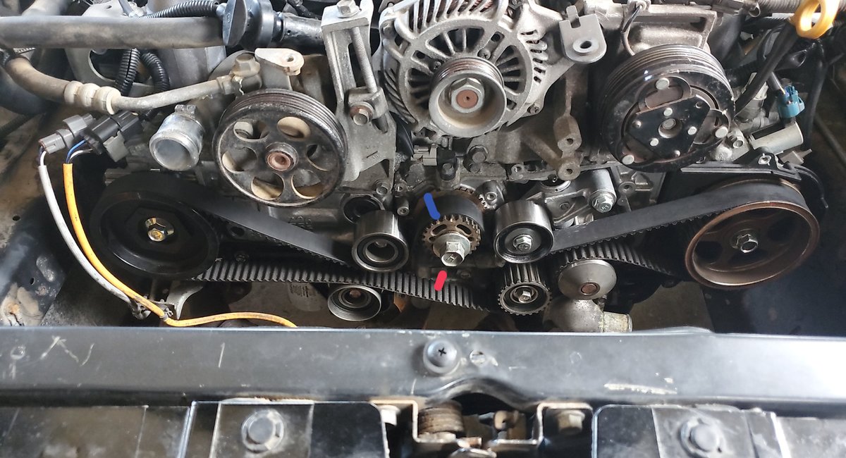
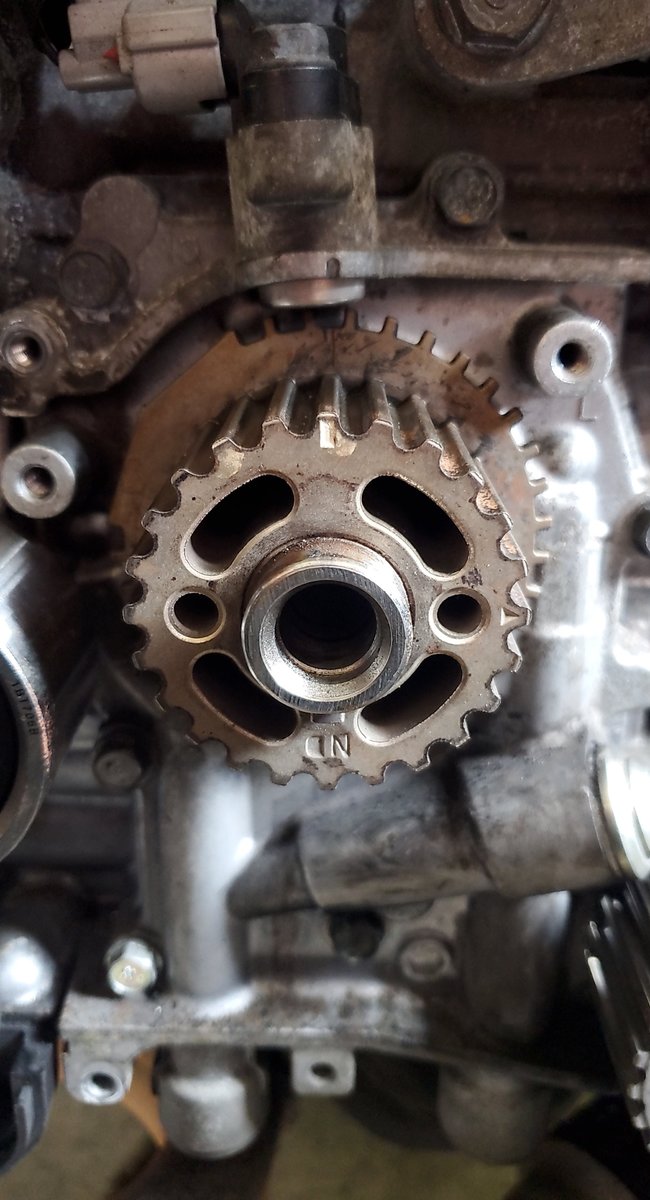
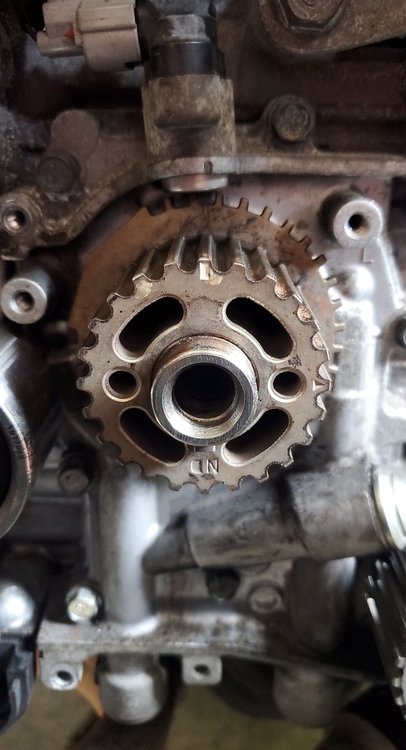
With crank lined up both cams spin freely, obviously with some resistance with the lobes though. All notches still line up after belt is installed and tensioner pin pulled. I posted a pic of where I'm at. You can see the white tic on the passenger side cam at 12 o'clock, the red tic on the driver side cam at 12 o'clock, and the white tic on the crank at 12 as well. I cannot go clockwise past the red animated dash nor can I go counterclockwise past the blue animated dash. I know I shouldn't roll it counterclockwise but it just happened. Can the cams be 180 degrees out of phase with the crank? I keep hearing the blockage sound like its coming from one of the valves on piston one but I have no idea how it would have gotten bent. Lastly, the timing belt I am using did make contact with itself while the tensioner backed out in the first place. The belt pretty much looks undamaged visually aside from a small amount of hardly worn down grooves. Do you think this could be enough to heat up the belt and cause it to expand? Thanks again for all your help.

-
So from what I understand to get to TDC on cylinder 1, I need to install the timing belt and rotate the crank until the arrow (not the tic mark) on the cam sprocket is pointing to 12 o'clock (passenger side). Only problem with that is that the blockage occurs before I can get to that mark. Any way to get to TDC and the correct cam orientation without having the belt on? Also, from what I can tell .008" has not fit in any of my intake valves. My spark plugs had a lot of gummy deposit on them as well as the boreholes to the plugs. Maybe a valve is just gummed up and stuck open.
-
How much wiggle are we talkin? I count the exhaust rocker on piston 3, one intake valve rocker on piston 3, and one intake valve rocker on piston 1 all barely loose. By loose I mean barely barely wiggling, but not rock solid like some of the other rocker arms. Thank you.
-
GD, So you're saying that if the valve lashes are good then this issue is really only due to me turning it over by hand? Could I potentially put it all together and just try giving the thing a start? The engine did not really have a rod knocking sound before this.
-
Bennie, The driver side cam sprocket is metal with a red painted notch. The passenger side cam sprocket is plastic with a white painted notch. I have both of these at the 12 o'clock position corresponding to the markings on the block/bracket.
-
I have attached a picture of how my crank is lined up when I try installing the belt. So I see (and am using) the white tab/groove on the front of the sprocket but it also appears that there is another tab on the same tooth on the rear of the sprocket. Is this what you are referring to? Or are you saying I should be using that rear sprocket as my reference and line it at the 12 o'clock position so that there aren't any teeth to the left of the 12 o'clock position when it's properly aligned? Thanks for the quick response.
- 20 replies
-
- 1
-

-
- timing
- bent valve
- (and 2 more)
-
Hey all. Last week I started up the soob (2009 Manual Impreza) and heard a light humming coming from the timing belt cover. Turns out that the belt tensioner in the timing belt assembly had slowly backed out of the block and was digging into the cover. I quickly pulled it into the shop before it got any worse and got to work digging into the problem. The tensioner bolt appeared to be stripped so I helicoiled its hole on the block and reinstalled the tensioner with no problems. White marks on crank and both camshafts lined up properly and pin pulled on the belt tensioner. I go to manually spin the crank to check my timing and I hit some kind of blockage at either 1/4 or 1/2 revolution, no matter what camshaft combination I try. I never cranked on it too hard and all 4 spark plugs are out so I know its not compression. I'm scared I somehow bent some valves. The sound appears to be coming from the passenger side of the engine so I took off the valve cover but am unsure of how to check if any valves are bent. I did use the starter and breaker bar to get my harmonic balancer bolt off which I read somewhere on here could be bad. The timing was still on when I did this though so I feel like it shouldn't have caused the issue. Could I have somehow bent my valves or am I doing something stupid?? Appreciate the help.


_LI.jpg.39a396e5d5fbf0990da2388d111dcb73.jpg)
_LI.jpg.208f9fcb1af46c1b1db77bdb0af371e5.jpg)