

pontoontodd
-
Posts
1894 -
Joined
-
Last visited
-
Days Won
40
Recent Profile Visitors
2837 profile views


pontoontodd's Achievements
Subaru Master (10/11)
271
Reputation
-
Swapping the struts in the field wasn't too bad. Definitely way less time consuming than taking them apart and swapping shims, bleeding them, reassembling, etc. Will try lubing the high lifts but they seem fairly clean and new. If anything the one I keep in the Impreza was too new, didn't have the paint worn off it when we started and I know that can be an issue.
-
Drove up to the UP Friday night and checked a few of the camping areas we'd found on the last trip. First one had a few people in it including some guys setting off fireworks so I went to the next one which was unoccupied. Camped near an outhouse along the river/reservoir and set up the tent. B showed up a few hours later. Saturday we headed to the first suspension test area. First thing in the morning the tach in the Impreza didn't work but then it started working after some driving and a few restarts and has been working fine since. Stopped at a cool waterfall/rapids at an old bridge/dam with some people fishing just downstream. Saw a Forester out in a field with the back sheet metal cut off. Took a few trails/roads we hadn't been on before that went through but I tried one too many. We'd gone north most of the way on this road before and then went east the long way so this time I tried going all the way north. It was fine until it wasn't. Got stuck in a mud hole in the Impreza. Took us a couple hours to get it out with the high lift and recovery ramps and snatch strap. Then it took us a few more hours to get both the cars turned around. Once we were out on foot digging and jacking it became clear the road was covered with 3-4” diameter logs. These were both a help and a hindrance. We did learn a few things though. One, we need to practice using our high lifts more or perhaps watch some videos. B's seems to just lock up occasionally. Mine wasn't lowering consistently. At one point I kept “lifting” even though it was mostly the jack sinking rather than the car lifting which then took a while to jack the jack out of the mud. I really need to fab a rear bumper for the Impreza with good recovery points. The 1.25” square adapter I bolted on my high lift was mostly useful but with all this heavy use started to rotate, so that could use an upgrade. Definitely need a bigger lifting foot too. I made one for the high lift I keep in the white Outback but it fits so tight I never bother to take it on and off so it makes the high lift even more of a hassle to store. Solving those issues probably would have cut our recovery time in half or less. Gotreads folding recovery ramps were alright. At least once they worked their magic, tire would suck them under and then grab. We slightly bent them but they still fold back in the carrying bag. Definitely more practical to carry than the solid recovery boards we have. We really need to pack the winch so it's more accessible too. Currently I have it buried in the spare tire well. There weren't many large trees around but we probably could have cut our time significantly by winching. While we were getting unstuck we found some scraps of styrofoam, part of a tow strap with hook that we used during our recovery, a floor mat probably from a UTV, a leather work glove, and a few beer cans. So we probably weren't the first people to get stuck there. At any rate, we got out and finally made it to the first suspension testing area. B could go significantly faster in the Forester than I was going in the Impreza without “bottoming”. The Impreza had the front end banging noise we've had in the Foresters that shows up sometimes even when we don't seem to be hitting very large obstactles. Got some baseline max speeds with slight bottoming on a relatively high speed road with some big but fairly smooth dips in it. We started with our tires at 35-40psi and then tried it again at 25psi, didn't notice much difference in ride quality. B did say the Forester seemed less squirrelly at the lower tire pressures, I felt the Impreza understeered less at the lower tire pressures. Just beyond that suspension test stretch is a log section where we were going about 10mph. Headed on to an area where we'd driven through a lot of whoops before. Unfortunately when we got there we found they'd graded most of them smooth. We did find one winding trail that was still whooped out though, very fun to rip through that at 35-40mph. Again the Impreza was limited by the banging noises. We headed on to the next section of whoops that's fairly close to a campground we've stayed at a few times. As we were approaching them it was dark and there was quite a bit of standing water in the trail so we decided to just camp for the night. Sunday morning we headed back up to the fast whoops. You can run most of these at 50-60mph but there are some near the end that are really big so 40-45 is more prudent. 60 will get you very airborne. Again the Impreza was limited by the banging and the Forester could go significantly faster. It was mainly the left front so we tried swapping front tires side to side (two different brands but both mud tires in the same size at the same pressures), that made no difference. We'd brought a set of front struts with different valving in them for the Forester and rear struts with different valving in the Impreza. Since the Impreza was limited by the front end banging and the front struts are easier to swap, we put the struts with new valving in the Forester and the ones off the Forester on the Impreza to see if it would fix the banging. B said the new strut valving felt generally more damped and didn't get as airborne off the same big whoops at the same speed. The struts off the Forester didn't seem better in the Impreza. We headed back to the winding whoops trail to test our changes. Similar results to the faster whoops. We were trying to figure out what might cause the banging noise and noticed the aluminum front control arm bushing on the corner that was making noise flexed a lot more than usual so we swapped that out with a less used spare. The banging noise almost went away, now I was able to drive the Impreza as fast as the Forester with minimal banging noises. This made sense as B has this problem most often, including the last trip, but we'd just replaced those bushings on his car before this trip. Then we headed back to the original test road. Again I was able to drive about as fast as the Forester with much less banging than before. There's a dip at the end that makes a decent jump in the one direction, the cars jump and land fine but at 50+ you're going a little fast for the dips right after the landing section so the cars bounce a bit. Also was able to drive the Impreza as fast as the Forester now through the logs with the fresher bushing. We swapped the front struts on the Impreza back to what we started with. Was maybe slightly better, we both felt that set we started on the front of the Forester was bouncier than the other setups which makes sense looking at the valving. We took the short (distance) way to the campsite which took a few hours. The longer distance way we took the next day takes about a half hour. Bounced the RR tire of the Impreza off a rock on the way there. Put a hole in the sidewall. Tried plugging it but even with three plugs it was still audibly leaking so we just swapped on the spare. Camped at a site we'd found on the last trip overlooking a stream/river. In the morning we headed up to town to meet my brother and take him for a ride and shoot some video since he's the real shock tuning expert. North of town there are tons of trails and we spent a little time wandering and found a wide powerline grade with two trails side by side, one whooped out, that we'd been on before and seemed good for shooting some video. Again the Impreza's coolant temp would start to climb on fairly low speed 2-3000RPM second gear light throttle type terrain especially with a lot of soft sand. As soon as we either stopped and idled or moved at a higher speed the temps came right back down. Still thinking that's the lean tune at low loads and RPM, need to set up another tune at stoich to test between the two. Met up with my brother and took him on a ride through the fun winding whoop trail and the side by side powerline whoops to get some video and took some notes on his thoughts. One thing B and I discussed since neither of the cars we took has functional AC at the moment is how much the 200F heater core under the dash increases cabin temps. Assuming once these cars are 20+ years old a fair amount of air leaks past the control flaps too. Will probably try some shutoff valves and some extra hose to bypass the heater core for summertime use and see if that helps. Even with the AC working, if it reduced cabin temps by 10F that would just improve AC performance further. Definitely seemed cooler driving the Impreza with the windows down to turn the fan off or switch to defrost/floor since the air coming out of the vents felt well above ambient. Overall it was a good weekend. Annoying being stuck that long in the heat and humidity but gave us/reinforced some ideas about improved vehicle recovery. Didn't execute the full original shock testing plan but we think we finally figured out the mysterious banging noise and it's a fairly easy fix and the valving changes we did make seemed to be an improvement. Also both cars seemed to go through the whoops pretty well.
-
Absolutely, wouldn't want to replace a rear diff in the field. With the auto, not as much of an issue to have a broken rear diff but could have been interesting. We don't trail ride that one much anymore but that's a good point, I should consider a torq locker.
-
The slop free shifter in the green Impreza took me a while to get the hang of but it's definitely an improvement. I haven't tested it much under hard braking but one time trying to stop going downhill on wet pavement the rears were locking so I should really put the bigger (2nd gen Legacy / 1st gen Forester) rotors and calipers on it sometime. Other than that one time it hasn't caused any issues. Stock airbox we put on the green Impreza was just one ~2.3" inlet going into a wall to swirl the air. We'd cut most of the wall out and added another hole a while back. I finally epoxied another tube on. Don't really expect this to improve flow but slightly less likely to get mud/water in the filter and puts the intake right at the bottom of the hood scoop. There was a little mud in the bottom of the airbox after the last trip. B cut a hole in the hood scoop baffle for the inlets. Can't see it too well. Should test it with and without that baffle to see if it affects intake air temps. Finally got a few good clock springs (thanks Slammo) and put one of those in the green Impreza, finally has cancelling turn signals and is ready for cruise control wiring. Put the one I'd been using back in the red Impreza. Also revalved and put different springs on the front struts off the black Outback so those are set up for our suspension test, they'll go on B's Forester. White Outback is super smooth under any kind of braking now. Guessing it was mostly the bushings but maybe the rotors too. White Outback's coolant temps started climbing fast a while back when stopped at stoplights in town. HVAC outside temp said 114F but it probably wasn't much over 90F. One of the fan fuses was blown, replaced that and it immediately flashed. Fan blade had come off (crimped/pressed/splined on) and the motor is very notchy and squeaky when turned by hand. Fortunately I'm a horrible packrat so I just swapped on one of the other H6 fans I have. Fuse and temps have been solid ever since. We also did some maintenance on the white Outback. I finally put the EZ36 alternator on it that I've had for over a year. We've had a couple alternators fail on that car, figure it won't hurt to have one that's only ten years old instead of twenty, plus it's a little higher output. Also replaced belt and idlers as those are known to fail. We changed the ATF and trans filter and rear diff fluid. Unfortunately these came out of the rear diff. The small spider gears are missing the tops of many of the teeth. Will get a picture when we remove it. Hasn't made any noise or caused any problems but I'm gathering parts for that replacement. Some bushings should be replaced while we have things apart.
-
First thing we did yesterday was swap out the long travel struts in the black Outback for some stock Outback/Legacy struts. We plan on revalving these shocks so we have a set ready to swap in the other cars for easier/faster shock tuning. It looks like a lowrider in person now. I'm pretty sure those are stock Legacy/Outback struts and springs but it does weigh significantly more than stock and the stock springs are pretty soft. White Outback has been shaking under moderate braking for months now. Light or heavy braking it's not too bad. Noticed a while back that the control arm bushings were shot so I replaced those. Have had this pair of Whiteline increased caster bushings for a while. Maybe easier to install than their normal bushings since they're not flanged. Only shifts the wheel about 1/4" which works out to about 1/2 a degree of caster. Also replaced the front rotors. Not sure if they were causing the shaking but we're going to need some used ones to turn down for rear use eventually anyhow. Replaced the air filter, it'd been 30k miles and it was super dusty. Still seemed to have good power though. Also replaced fuel filter and front diff fluid. B replaced the taillights on his blue Forester, they've been cracked and leaking for a while. He tried replacing the AC condenser since it had rubbed through on the radiator but apparently the 2001 Forester condenser is different than the good 2000 Forester condenser he had. Also replaced his trans fluid and some other things. Got the STI shift yoke from the dealer. In retrospect I should have just modified the one I'd welded and ground the holes on to clock it but this was easy. Replaced the bushings. Centered up, way less slop, can now fit the shift boot and trim on.
-
B and I weighed his blue Forester and my green Impreza loaded with our usual off road trip cargo but no camping gear. Blue Forester weighs 3739#. With both of us sitting in it, 4126#. Either way it's super close to 50/50 front/rear weight. Green Impreza weighs 3714#. With both of us sitting in it, 4102#. Either way about 150# more on the front than rear. I was a little surprised it was that heavy, with no cargo it was 3245# a month or so ago. So we started unpacking it, with a few bottles of oil still in it we got it under 3300#. So we had over 400# of tools, spares, recovery gear, tow bar, etc. This stuff really adds up. Just a couple folding recovery ramps and a couple straps was 30#. Definitely not as much volume as we used to pack in the black Outback but apparently most of the weight. Will have to keep working on packing lighter. Lateral bumper support tubes rubbed a little on the front tires and the tires aren't fresh so I wanted to add some clearance. Gas tank guard has already been put to use. Looked over the front end of the white Outback. It's been shaking increasingly worse at certain brake pressures, seems like both the front lower control arm bushings in the aluminum brackets are sloppy. At some point I'll probably replace those and the rotors. B replaced the LF rear lower control arm bushing in the Forester, it was shot. I noticed as we were driving home from the UP the LR of the Forester would change camber occasionally, maybe when cornering but it was hard to tell. We noticed this. B took the link out, replaced the bushings (bolt was frozen in one), welded that piece back in and ground it flush, welded and painted a thick washer over the top, and reassembled everything.
-
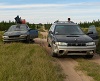
Drove up to Z's Friday night. He noticed one of the brake lights in the Impreza was (artistically) burned out so we went to Oreillys and got a pair of bulbs. B met us at Z's, we headed up and camped in northern WI. Saturday morning we headed north and Z took us on some ORV trails north of there so we headed north on those. Within four miles we saw a black bear and a bald eagle and some other wildlife. The main one Z had intended to take us on is ATV only. So we just drove up to the UP. Started out in an area north of Norway we'd only been through once and found some other trails and potential campsites there. Next two pictures are of one of the fairly long rocky hillclimbs (by UP standards) we did that weekend. Saw a wolf pup(?) walking down a side road, took a few pictures and let it be and got to the (nearby) dead end. Found a hillside with some big sandy hillclimbs so I tried one but stalled out and backed down when it got too off camber. Hit a different one and made it to the top. Found a human shaped sculpture made out of chainsaw parts. This sign was a bit misleading, while the road was rough by many peoples' standards, it was about average for what we drove on that weekend. Got to a man made dam that appeared to have blown out and then repaired by beavers. At the bottom where we had to drive by it there was a big leech sucking on a dead crayfish. Forester had been making a lot of exhaust noise under load so we stopped to fix that. One of the bolts had fallen out of one of the exhaust flanges so we found a nut and bolt and B got it back together while I cooked some burgers. Z spotted a big Eastern Fox snake in the trail. Wandered north and hit a bunch of trails and found a giant pile of potatoes in the woods. About a mile from the nearest farm, not sure if it was just a handy berm construction material or if they just needed to dump a bunch of potatoes. We had decided to go up to Craig Lake as B and Z hadn't been there before. Drove up to a campground and stayed the night. One of the random assortments of decorations we've seen in the UP over the years. This is miles from pavement. This weekend was a good demonstration that you never know what you'll find in the UP. Came across several beaver dams that were flooding old roads we were trying to follow. Got to a wetlands reserve and hiked in there a mile or so. Unfortunately we got up near Craig Lake to find that it's closed for the summer for maintenance. Hit some trails and did a little hiking and then camped in that area. Saw a ruffed grouse alongside the trail. It was jumping around and fanning its tailfeathers etc. It was on the passenger side and I looked out the drivers side while Z was taking pictures and saw what looked like a mouse on the ground. I went to take a picture of it and realized it was a chick so we continued on. Monday morning we went down a snowmobile trail to start wandering back home, it was eventually flooded so we found a different trail and headed south. Hit a stunt area we found last year and did a few hillclimbs. Impreza had a lot of wheelspin and rev limiter in first gear climbing a fairly steep one. Saw a turtle wandering around. Went through an area we'd been years ago that looks significantly different now, some berms gone, other berms added, trees growing up in areas that had been clearcut, etc. Found one stretch that would be good for suspension testing/tuning. A mile or so with decent sized dips and bumps and another section that's quite rough with holes in between small logs. Wound up taking a few narrow trails that went on for miles and surprised me by connecting to main trails. We took a tour of an old iron mine that was interesting. Drove through part of the southern UP we hadn't explored before with some decent camping areas. Saw a lot of turtles and some muskrats. Aired up and drove home on pavement. Lots of rain on the way home. I'm a little surprised the Impreza doesn't seem to have any leaks or electrical problems even driving through heavy rain for hours, I've done it a few times now. Overall a good weekend. No major issues, never even got stuck or got a flat tire. Impreza is great on the trails. Not used to having good rear visibility, way easier to back out of trails and the shorter wheelbase and rear overhang make it easier to turn around in the woods. The 60% rear bias and light rear end and open center diff make it handle almost like a rear wheel drive car. It was never close to actually spinning out but it has power oversteer in second or third or even fifth gear sometimes off pavement. Surprised me once in first gear on wet pavement. Steering seems to be a little quicker than the Outbacks which helps in those situations. There was one time on Saturday when B was driving it and he got stuck in a soft muddy trail. I could see just the rear tires spinning. He locked the center diff, all four tires started spinning, and he was able to drive out. It's easiest to lock and unlock when moving, never makes any grinding noises, helps to pump the clutch. So if we were in a really rough or muddy or sandy section I'd just lock the center diff for a while until we got back to some easier trails and then unlock it. Never used the low range all weekend. There was at least one hill I climbed in first gear high range that B had to use low range in the Forester to climb. Some things I like about it aren't from our doing but just because it isn't as beat and rusty as the black Outback. You can drive around with the windows down without choking on exhaust fumes, drive through all kinds of water and rain without getting any in the car. Found myself keeping it under 2000RPM most of the time and it had plenty of torque for normal trail riding. Fans ran more than I expected, when we'd start going really slow or stopping and starting the temps would creep up and at least one would kick in and then basically stay on until we shut off the car for a while but temps never got much above normal. As soon as we were moving the temps would drop back to the normal spot. Wondering if this is partially caused by our current tune being lean at part throttle at 2-3000RPM in an attempt to save fuel. Seemed like it would run a little cooler at 1500RPM where it's probably running richer. Probably a couple times a day after nearly stalling the engine it would start running rough. I just shut it off and restart it and then it would run smooth. Impreza might get a little better fuel economy than Forester on the road but worse on the trails. Might be something wrong with the fuel filler on the Impreza, on the last couple fillups it didn't seem to actually fill the tank. I've noticed recently you can feel crosswinds push you around. Not dangerously like an air cooled VW but something I never notice driving Legacy Outbacks.
-
Installed V band clamps on the headers. Turned some aluminum slugs to align the various pieces. Mockup assembly, I had to cut the Y pipe back beyond those grooves. Siliconed some pieces of silicone under the C shaped pads I'd welded on the crossmember to keep the top of the exhaust from denting. Meant to do this a while ago, hoping it minimizes the noise of the exhaust banging against things. V bands welded and exhaust assembled. Exhaust is much quieter now on the throttle, seems to have eliminated the raspy exhaust leak noise. Still sounds good under load though. At about 60mph the exhaust is so quiet you can barely hear it, at least over the tire/bearing noise. At about 80mph you can definitely hear the exhaust but it's not obnoxious. I did get a slightly longer muffler I want to try out sometime too.
-
Just made this shock tuning video public. Best jump starts at 0:27. Stay to the end for a laugh. https://youtu.be/3hFvQLtI2kQ
-
I replaced the front shock hose on the Impreza. Seems like that spring perch just rotated out of place, hopefully won't be a problem in the future. We took it and the blue Forester to our friend's little jumps. Forester seemed to jump a little better than Impreza. Impreza seemed to nose over more and was probably bottoming out the front suspension on landing when hitting the jump fairly hard. Also got video driving over parking barrier as a baseline for shock tuning. Did all that with 40psi in the Impreza's front tires though. When we got home I put softer springs on the rear of the Impreza. Only sits about 1/4" lower initially but will probably settle down a bit after some use. Replaced one of the rear CV boots that had a little rip while I was at it. Didn't get back out to test jumping for various reasons, curious to see if the softer rear springs help. The gas pedal in the Impreza seemed too far to the left so I tried to just bend the rod to the right. Was working for a while until the plastic barrel it rides in exploded. So don't do that. Got it super glued and safety wired back together and seems to work. Surprisingly open design. Gasket on the black plastic part probably seals against the sheet metal. Bought a used replacement off ebay, guess I'll have a spare. Meanwhile B's main project on the blue Forester was removing and replacing the stud for the lateral links out of his knuckle. Welded a 14mm nut to an acme nut and used my hollow hydraulic cylinder to pull it out. I'm working on replacing the two bolt flange connections in the Impreza exhaust with V band clamps. Will post pictures when that's finished.
-
I've owned the green Impreza for (checks notes) 22 months now. Definitely the longest I've ever had anything on jackstands. Happy with how it turned out though. The power to weight ratio makes low range almost unnecessary but it's nice to have that for when I need it. The big front axles, bolt on wheel bearings, and real parking brake with the billet knuckles definitely gives me some peace of mind too. I just updated the EZ36 swap page too. Still have some photos to add there and once I finish the wiring I'll have to update it again. Also have to figure out some way to share the base map, a lot of this info is kinda useless without it. Worst case I'll share it on my website. Tell me if there's anything I should add/edit on the swap page.
-
Will try to find/post better pictures eventually but for the cooling system we settled on a modified Miata radiator. Pushed the condenser as far forward as we could with minimal cutting/bending/hammering. Flipped the condenser brackets IIRC, put some rubber in between it and the body. Seemed like a stock H6 radiator would have fit but it would have been rubbing on the timing cover. Cut and welded some water necks on the Miata radiator to fit the H6. This is one of my biggest disappointments of the swap, it might be worth using a second gen Impreza just so you could run a stock H6 radiator. While we had the water necks cut off it seemed that part of the tube they welded in might be blocking flow. So we ground that out. Probably won't matter but I want as much cooling capacity as I can get. Used a cheap universal fit coolant overflow tank, I've used these on a couple cars/trucks and they seem to hold up. Swapped to a 13psi cap from the 20psi cap the radiator came with and the level in the overflow seems to go up and down with coolant temp as you'd expect. Using two pusher fans. For the intake we just modified a Can Am airbox to pull air in from the scoop. One downside is that filters are fairly expensive and not really available retail. Put a water repellent filter sock on it too. Installed the grommet and air intake temp sensor for EZ30 in it. Also have a couple cone air filters. Plan to eventually test them on the dyno and then cut the baffle under the hood scoop appropriately.
-
Hose clearance to the spring perch is pretty tight, seems like maybe the spring perch rotated (we cut some extra clearance on the side with the hose). Easy fix but will have to see how it holds up long term. Should be the same as our other cars and we haven't had problems with the hoses on those for years.
-
I don't think it was the injector being clogged but probably a loose wire connection. The engine harness connector just doesn't seem right. There's 54 pins in five rows and the three small rows are difficult to insert the wires into without kinking. I'm thinking about replacing it, maybe with a few 20ish pin connectors (open to suggestion there). When you flex it around it will cause the engine to run well or poorly. I got it to run decent and taped that connector up and it ran well for a few days. We've been planning on going to the Badlands off road park today for a month or so now. This weekend they allowed 2WD buggies which they normally don't. One of our buddies we used to race with was planning on bringing his buggy so we wanted to meet him there. Yesterday B's blue Forester was running rough again and he eventually noticed the fuel coming out of the fuel filter looked like coffee but the fuel going in to the filter looked clear. So somehow the fuel filter had started pushing dirt into the engine. He replaced that and the complete intake with injectors. Then it ran fine. C and I headed down in the green Impreza. Aside from the lack of cruise control, AC, a speedometer, etc. our drive went fine. We're pretty sure the rasp in the exhaust is one or both collector gaskets, I want to replace them with V bands. At light load there's no rasp and the exhaust is actually fairly quiet. We got a message on the way down that B's Forester started running like crap or not at all after they filled up with gas. C told him he'd had the same problem with his Subaru Baja and he just had to run it at full throttle when it was full of gas. We're guessing it's getting fuel in the vent/evap system and flooding the engine. B was able to get it going again. Meanwhile C and I checked in and started wandering the off road park looking for J. The green Impreza has no problem cruising around the tailing piles (similar to pea gravel). I was mostly cruising around in second. Only a few times all day did I need to use first on some fairly steep hills. B had to use low range on at least one of those. I had the center diff unlocked all day and it got quite a bit of rear wheelspin. It will slide the rear end out a bit but nowhere near enough to spin. I didn't think about it until we got back but I should have tried locking the center diff and seeing how it did. We eventually found J and followed him around a bit in his buggy until B showed up. We mostly drove around on the tailing piles as J's buggy is too wide for some of the trails but we did hit some of those too. J's buggy can easily eat up the rolling whoops at high speeds. We swapped back and forth to the different cars during the day. After we'd been riding for a while Z was driving the Impreza and said it started running rough. I was able to push the wire harness into the connector and get it to run smooth and taped it in that position and it ran fine the rest of the day. With the heat in the engine compartment that connection had gotten significantly softer than when at room temperature, something I should keep in mind. The light weight and high horsepower/torque of the Impreza was great for just getting around and climbing hills. I exceeded the limits of the approach angle a few times but just in the tailings. We'd noticed a looseness in the RF corner of the Impreza and eventually C noticed it was leaking shock oil. Went back to the campground and took the shock off and the hose was kinked and caused it to start leaking. We were running out of time so we headed into town for dinner. Drove back home fine. We were disappointed that only a few buggies showed up to the park that we saw but glad we got to ride in J's. Probably drove over 500 miles and burned about 25 gallons of gas, overall a solid first run for the Impreza. Also the first real test of the billet rear knuckles / front CV axles in rear setup. Even at about 10 degrees at ride height and some occasional wheel hop in the tailing piles they survived the day. I will probably put slightly softer springs on the rear to cut that down a bit.
-
I used Raptor headers that we shortened about 1" for more ground clearance. Extended one side with stainless for better clearance between axle and O2 sensor and flange. Not hard to believe these headers add about 10% more power over stock. A better solution might be to build a set with primaries that are all next to and level with each other for more ground clearance. The Y is constructed out of 2.25" 4130. The middle portion is 2.5" 4130 with a V band to a resonator. Should have used V bands for the ends of the headers. At light loads the exhaust is pretty quiet but at anything about 1/4 or 1/2 throttle it gets raspy. Sounds like it's coming from the header flange gaskets. Will probably replace those with V bands, thought about doing that from the beginning but they already had the flanges welded on them.
