Leaderboard
-

Brianmitchtay
Members3Points85Posts -
GeneralDisorder
Members2Points23391Posts -
1 Lucky Texan
Members1Points10144Posts -

Loyale 2.7 Turbo
Members1Points7843Posts


Popular Content
Showing content with the highest reputation on 01/18/20 in all areas
-
2 pointsThere really is no significant performance to be had on the NA 2.5's. Volumetric efficiency is already quite high. GD2 points
-
1 pointwww.boxer4racing used to carry go-fast bits for legacy chassis - dunno what they might offer for the very new models. got my Strommung muffler for my WRX from them. Very responsive to my email questions. That was long ago.1 point
-
1 pointHopefully this helps! and good luck! All the wires around my SPFI control box are so stiff and old that when I move them around to check continuity and resistances I always feel like I'm probably breaking more wires and causing more harm than good. ha

 1 point
 -
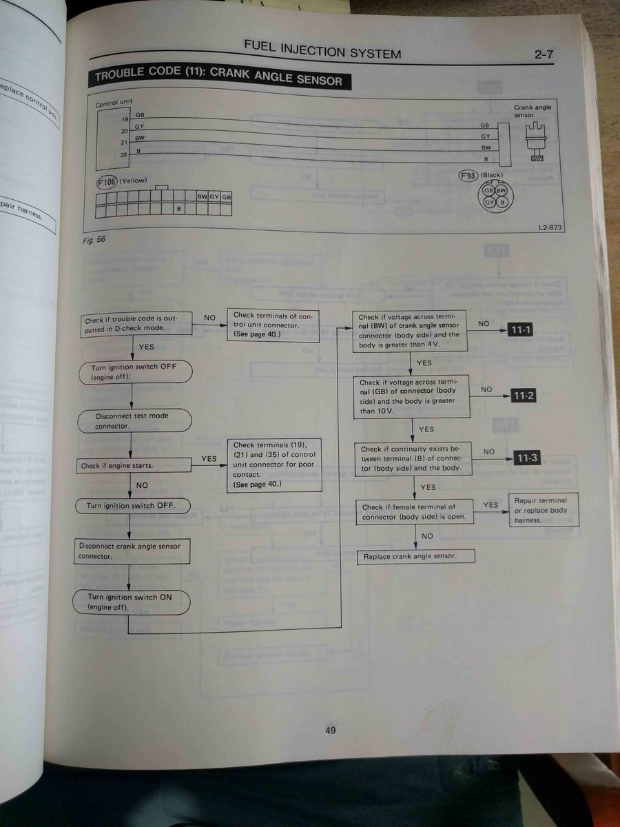
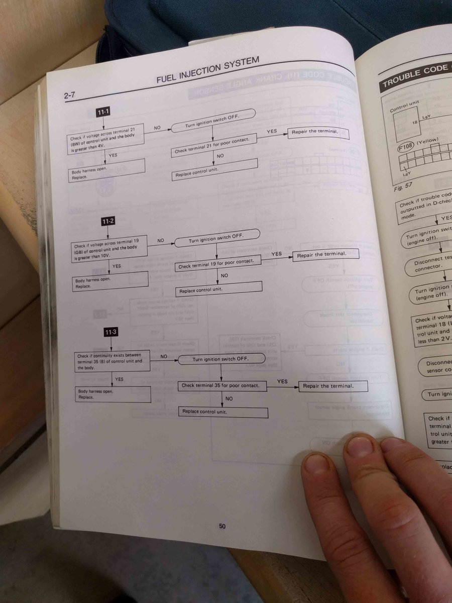
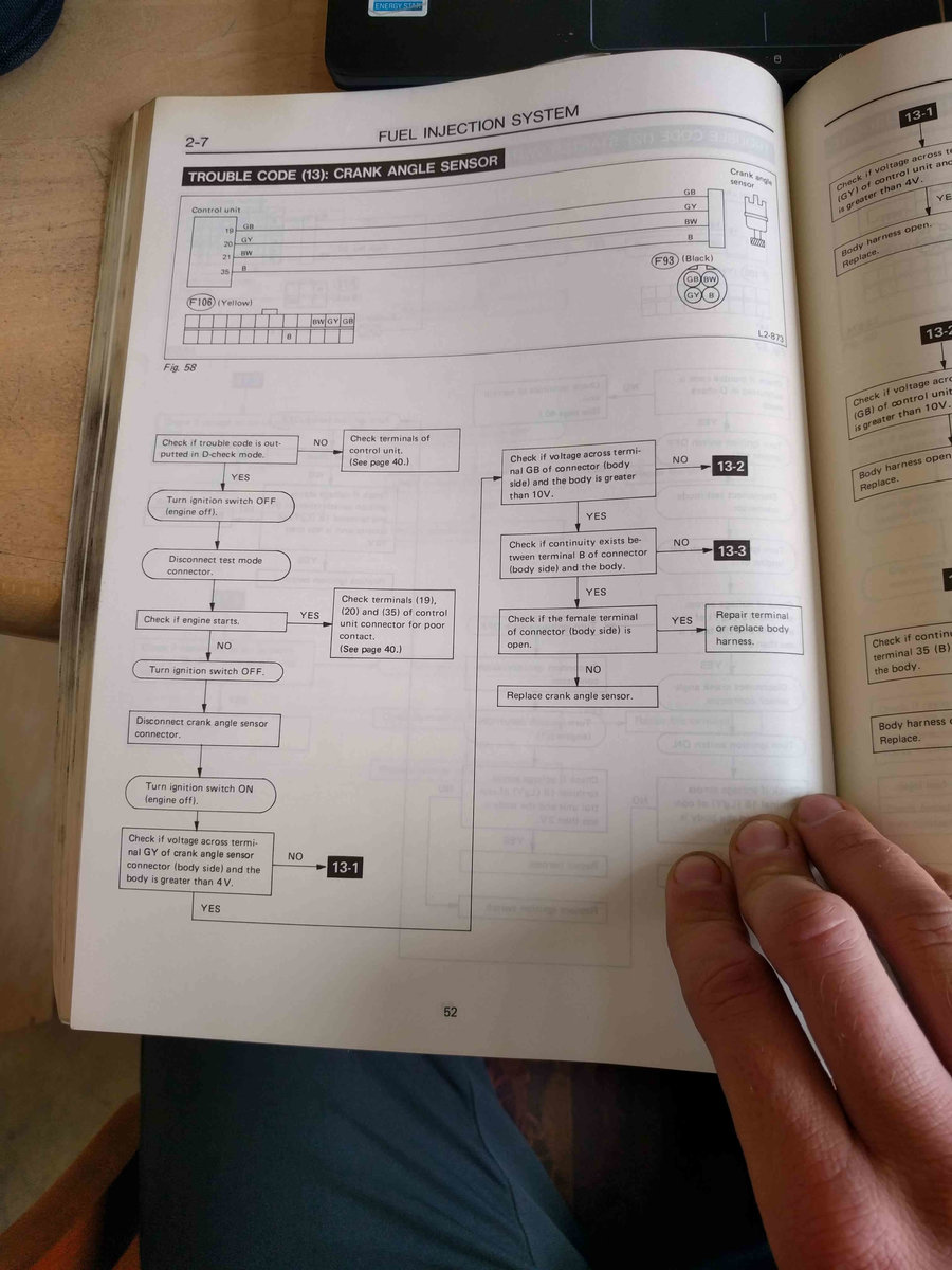
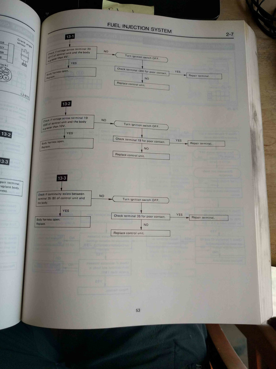
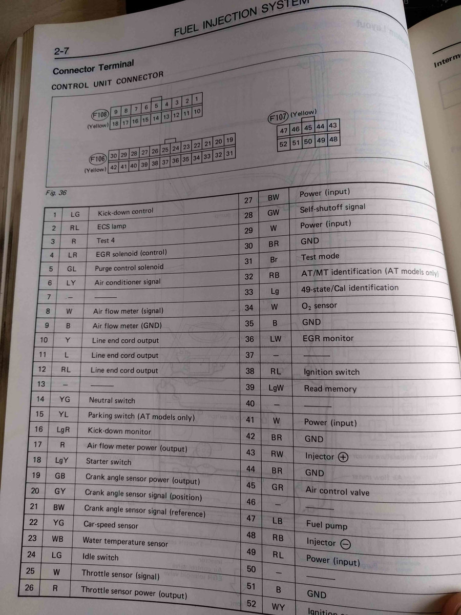
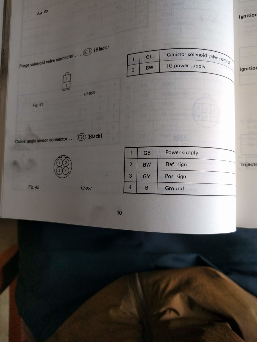
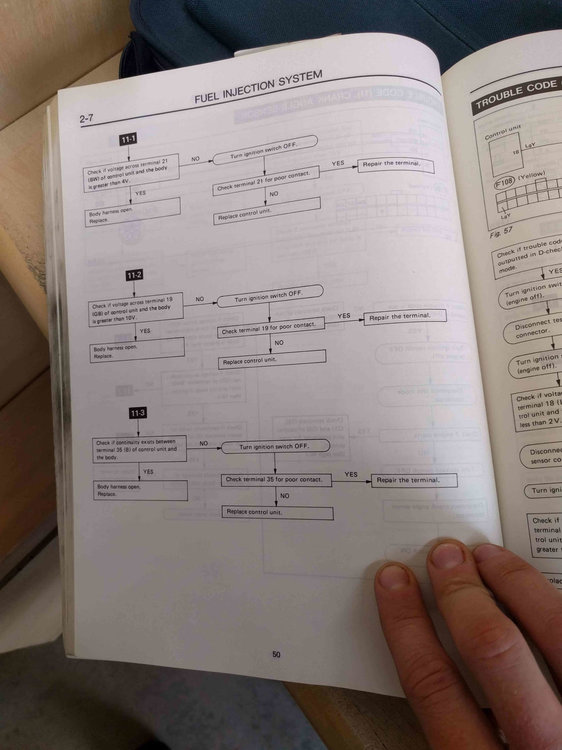
1 point1 point1 pointOk so far as I can tell, in the SPFI section of the fuel injection chapter there's some info on troubleshooting the two possible trouble codes, 11 (no reference pulse) and 13 (no position pulse). also a wiring diagram of the sensor. I'll post those as well as the diagram of the layout of the control unit connectors. That should probably be what you'd need to check all the wiring. It says there's a more thorough write up of the distributor and ignition coil setup (including crank angle sensor) in another volume - Chapter 6-1 Engine electrical system. If you'd like I can pull that one out and see what it says. I'll be at the library all day today so just say the word if you see this post in time.
 1 pointWiring New Relays Basically talkin', you only need three (3) wires in order to get a Relay properly working, to Power a Device (Such like Horn, Halogens, etc...) 1► the Positive input shall be placed in two Spades, the Nº 30 (which is the High Power positive imput, directly from battery - To be Transferred to the Device once the Relay is On) and to the Spade Nº 86 (Positive switchin' signal) and those could have power permanently. 2► The Switching (On / Off) Signal, comes in from the Ground, sent by a Grounded Switch on the Dashboard (or wherever you might want to put the Ground source, such like a High / Low Beams' stick, Horn button, etc...) It goes to Spade Nº 85 3► The Positive Power Output to Power the Device, (Halogens, Horn, etc...) goes out from Spade Nº 87 Of course you could use a Positive signal (+) to switch the Relay on /off instead the Ground, But that's a Four (4) wiring install. In such case, the Relay's ground shall be Permanently connected to Spade Nº 85, and the Direct Positive imput shall goes to Spade Nº 30 ONLY, then you use a Low power positive as Switching signal on Spade Nº 86. Remember: Nº 87 is always the Power Output for the Device. _______________________________________________________________________________________________________ I have a couple of Pictorial Diagrams to Help you in How to Wire New Relays; you can find one of those in my other writeup, named: ~► "How to Wire Dual Electric Fans on a Subaru EA82" This is the Picture: Also I posted another Pictorial Diagram, in my Wife's car Thread: ~► "The KiaStein" This is the Picture: If you find this writeup, Useful, please let me know by hitting the "Like" Button below. I only ask this as a Motivation to continue Sharing my work with you. Kind Regards.1 point