Leaderboard
-
idosubaru
Members3Points26995Posts -
rallybru310
Members2Points29Posts -
TXJayhawk
Members1Points45Posts -
Rampage
Members1Points683Posts


Popular Content
Showing content with the highest reputation on 03/10/20 in all areas
-
3 pointsCrank case ventilation A hose connects from there to a metal tree which has 4 additional hoses connecting to the: 1. intake (see the ports on the picture of the bottom of an XT6 intake hose) 2. one for each valve covers (see the port on the top of each valve cover) 3. And the top most of the tree goes to the PCV valve in the intake manifold3 points
-
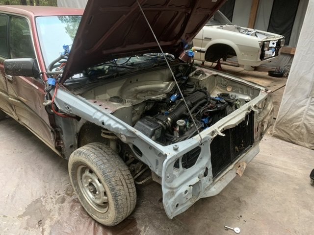
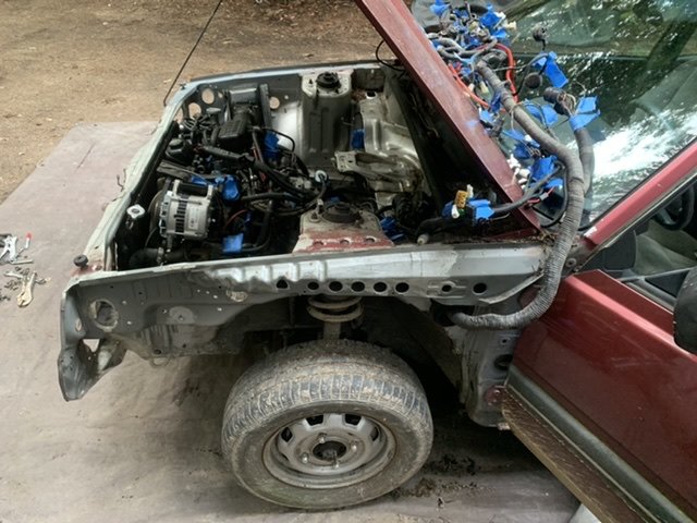
I came hone from work to find my son had finished unplumbing things and had totally labeled and removed the wiring harness!!!
 1 point
 -
This is Awesome! Keep the pictures and posts coming1 point
-
i found the fault. it was a screw that had went through the wiring harness behind the passenger headlight when i mounted the ballast for the hid's not sure why it dident trigger a code sooner but after working through everything ive done recently i found the issue1 point
-
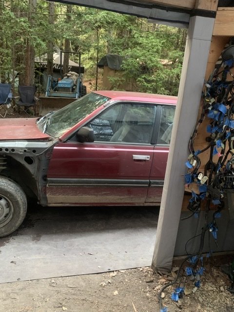
Thanks to Crazyeights misfortune we now have a second donor vehicle with many fresh components. I look forward to resurrecting what we can from “lil red”. We did let “lil red” stretch it’s legs one more time before we started dismantling it. We had so much fun on our first pass that we drove back down to the bottom of the mountain and went again, such a shame it got smashed! Thanks for everything Crazyeights!
 1 point
 -
1 point
-
No, you cannot bypass it. The transistor in the control unit will not handle the current of the coil. How many wires on it and is it grounded to the coil bracket? To act as a transistor power switch for the coil it would have a signal input, a ground and an output to the coil. What it does is, take the high current load of the coil away from the SPFI Control Unit, or ECU or ECM in later models. It is the same process as produced by using a relay. A small current can control a large current. Transistors can switch on and off really fast like millions of times per second. I was looking at wiring diagrams and you may be able to wire in a later model Igniter in place of the Power Transistor. The Igniter is basically the same thing, only it is built to run two coils in a pack instead of one coil. I looked at the 95 and 97 Legacy because we have them. Remove one of the two wires on the coil terminals. With the key on, there should be battery voltage on one of the two wires. The one that does not show voltage goes to the Power Transistor. Remember which one that is. To test the coil hook up a spark plug wire to the coil and a spark plug. Ground the spark plug body somewhere on the engine. Turn the key on and take a wire grounded on one end and tap the other end on the coil terminal that goes to the Transistor. Do not hold it on the terminal, just tap it. There should be a spark when you remove the wire from the terminal. When the wire touches the terminal the coil generates a magnetic field. When the wire is removed that magnetic field collapses and produces a spark. The input wire to the Power Transistor should show a low voltage pulse on a volt meter when cranking the engine. What I don't know is the impedance (electrical resistance at certain frequencies) of the old coil compared to the newer coils. There will be a capacitor (or condenser) either external or built into the Power Transistor. That capacitor is used to complete the coil circuit to ground when the transistor switches off and the magnetic field collapses and produces current in the high voltage winding of the ignition coil. If you decide to try wiring in the Igniter, the following is how to wire it. Go to a yard and get the Igniter and plug. Cut the wire harness long, so you have wires to work with. You can trim off the wires later. It is mounted at the center of the firewall on the bracket for the support that goes to the top of the bellhousing. Remove the Power Transistor. On the Igniter connector there are 6 terminals but only 5 Pins are used. Pin 3 has a black wire, so you can easily decode the other pins. Wire colors. First letter is wire color. Second letter is the stripe color. Black, Green, Lavender, Red, Yellow, Violet. Pin # and Wire color. Pins 1 YL & 2 YV - connect the wires together and they go to the signal Input wire that originally went to the Power Transistor. Pins 5 L & 6 RG - connect the wires together and they go to the coil terminal. Pin 3 B - goes to a GOOD ground. I wish I had something to try this on, but I don't. Connecting the wires together hooks the two transistors in parallel so the coil current is divided between them. What I do not know is what the combined input load will put on the computer signal. It depends on the resistor circuit for the transistors built into the Igniter. We may have to break it down to just one circuit. Let us know if you try it and how it works out.1 point