All Activity
- Today
-
I know that feeling. I have an EJ turbo conversion on the go for the last four years. I’ve barely touched it in the last year. It’ll get there. Cheers Bennie
-

2.2 OBD2 swap into ‘85 Brat
Greentractorfarmer replied to Greentractorfarmer's topic in Old Gen.: 80's GL/DL/XT/Loyales...
Correct, the engine and wiring from the first GL swap are installed in the current Brat GL. I have a fuel pressure gauge, downstream of the filter, rigged just as you describe so it can be read when driving. 38-40 psi at idle, high 40’s when throttle opens, and holds when shut down. Actually the pressure slowly rises from 38 to 45 at engine off, holds at there for a hour, then slowly falls to zero over several hours. I think the pressure increase at engine off is heat expansion and assume the injector system is okay since it holds awhile before decreasing. The tank always pressurizes quite a bit, to the point that gas vapor smell is obvious, probably through the gas cap vent. This seems to be the only difference in the first GL with this engine and the current Brat GL-buckeroo. Your statement about the oscilloscope is helpful. It’s what I’ve been thinking is next step. (This particular model 2.2 didn’t use MAF, instead has manifold pressure sensor plus intake air temperature sensor.) I will need to get a shop to do this, but am concerned the Frankenstein aspect might add difficulty to getting that help. I’ve tried to use live data on my reader, but don’t get far. I also have back-probed at the ECU to read voltages of various sensor signal while driving, all looks solid. But the scope can show oscillations, while the meter only shows steady 12v at the injectors, for example. Thank you for the input. It’s encouraging. -

EA82 spark timing puzzle
el_freddo replied to el_freddo's topic in Old Gen.: 80's GL/DL/XT/Loyales...
The L went with its owner this morning, no time to tinker so couldn’t test the mechanical advance. Haven’t heard from them so all must be well enough… Cheers Bennie -
Thanks! It appears someone definitely paid for the undercoating and it paid off. I've only seen some very minor flaking on the front bumper attachment points.
-

Reason for a Melted Distributor Rotor?
SuspiciousPizza replied to LaMamelle's topic in Old Gen.: 80's GL/DL/XT/Loyales...
First thought that comes to my mind is the bearing failed, the shaft got some weeble-wobble and cooked the bearing. Heat went up the shaft and cooked the rotor. If this is an optical distributor, I'd be curious of the condition of the "eye" (the little donut-shaped module that sits under the rotor beneath the metal shield.) That eye module is also made of plastic. It may have also been damaged if this is a toasty bearing scenario. :] -
Just realised your plates are very similar in number to my green sedan JK4474 - mine is registered as a 1989, so yours must be a very late 79 rego, and mine a very early 1980! Would be keen to see some progress pics if there's any? Cheers
-
Man, it has been too long since the last update! Gertie is still kicking, still WOFed, and still in need of the EJ swap and certification. Life gets in the way of grand plans sometimes, but they are still in motion.
-

EZ30R AVLS Cam Specs deep dive
donkeytits1 replied to donkeytits1's topic in NA Fuel Injection Engine Tech
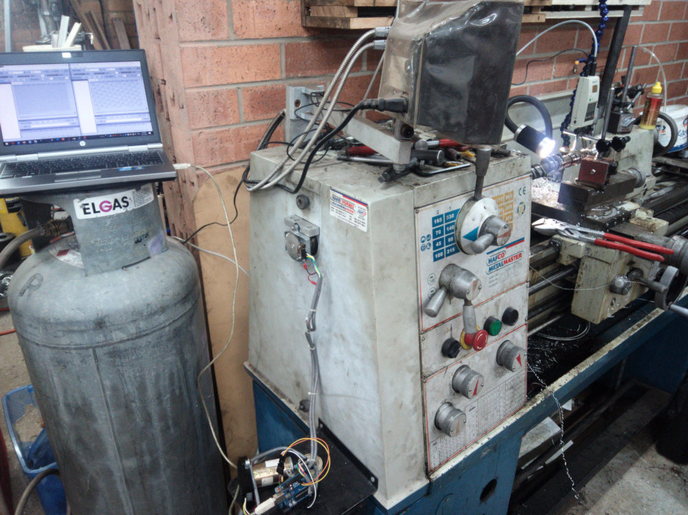
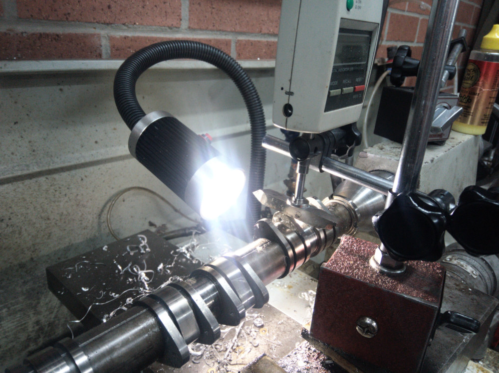
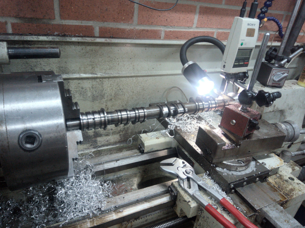
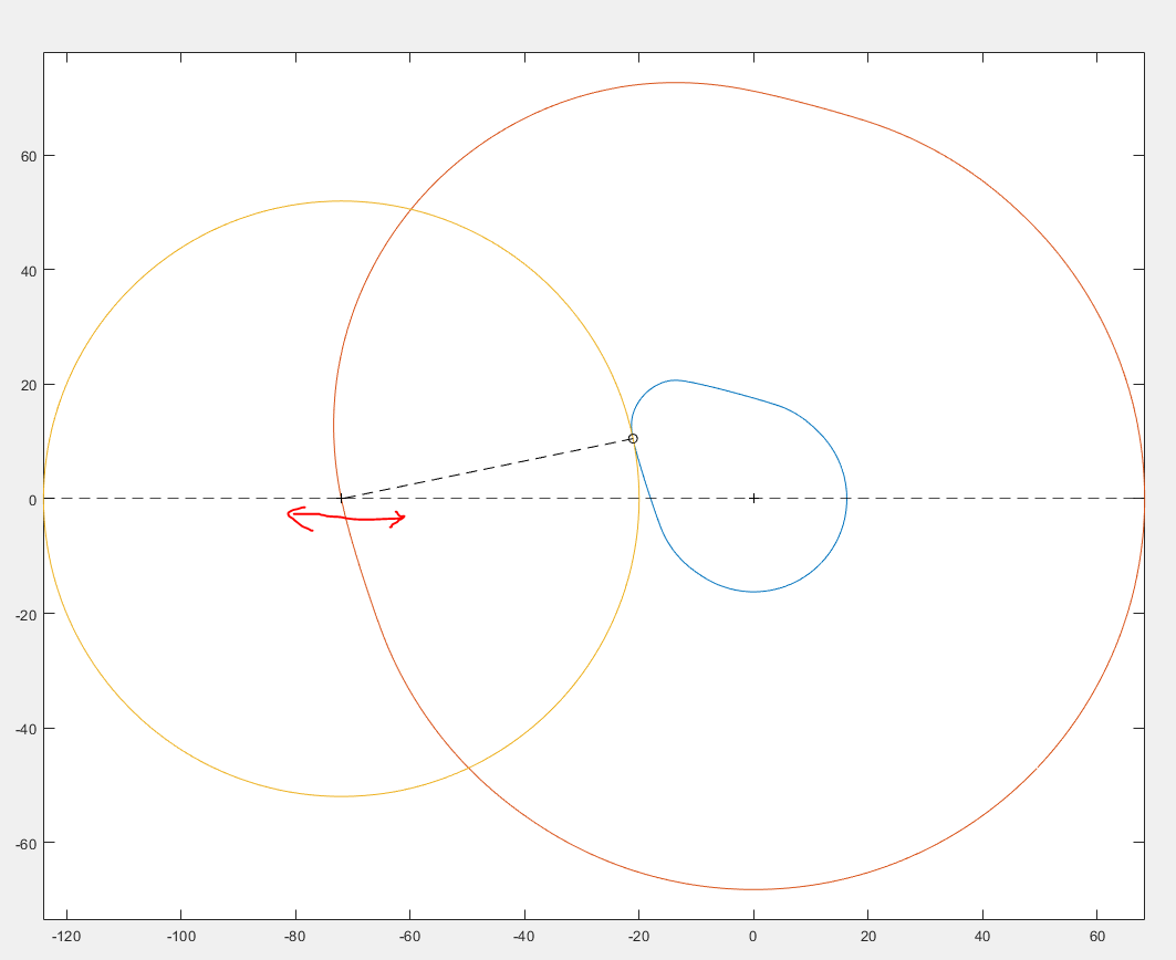
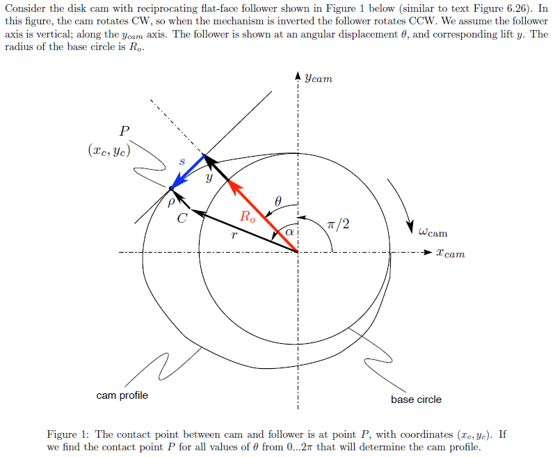
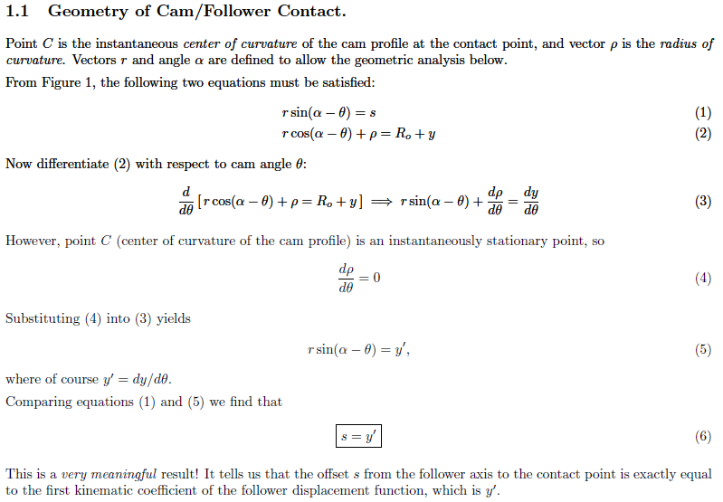
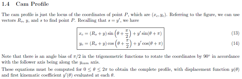
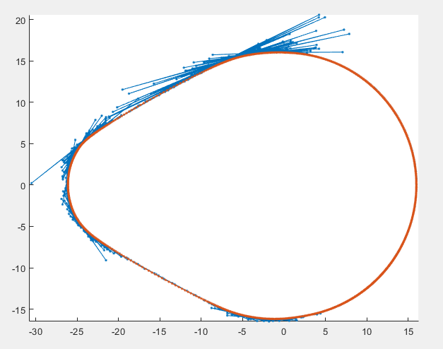
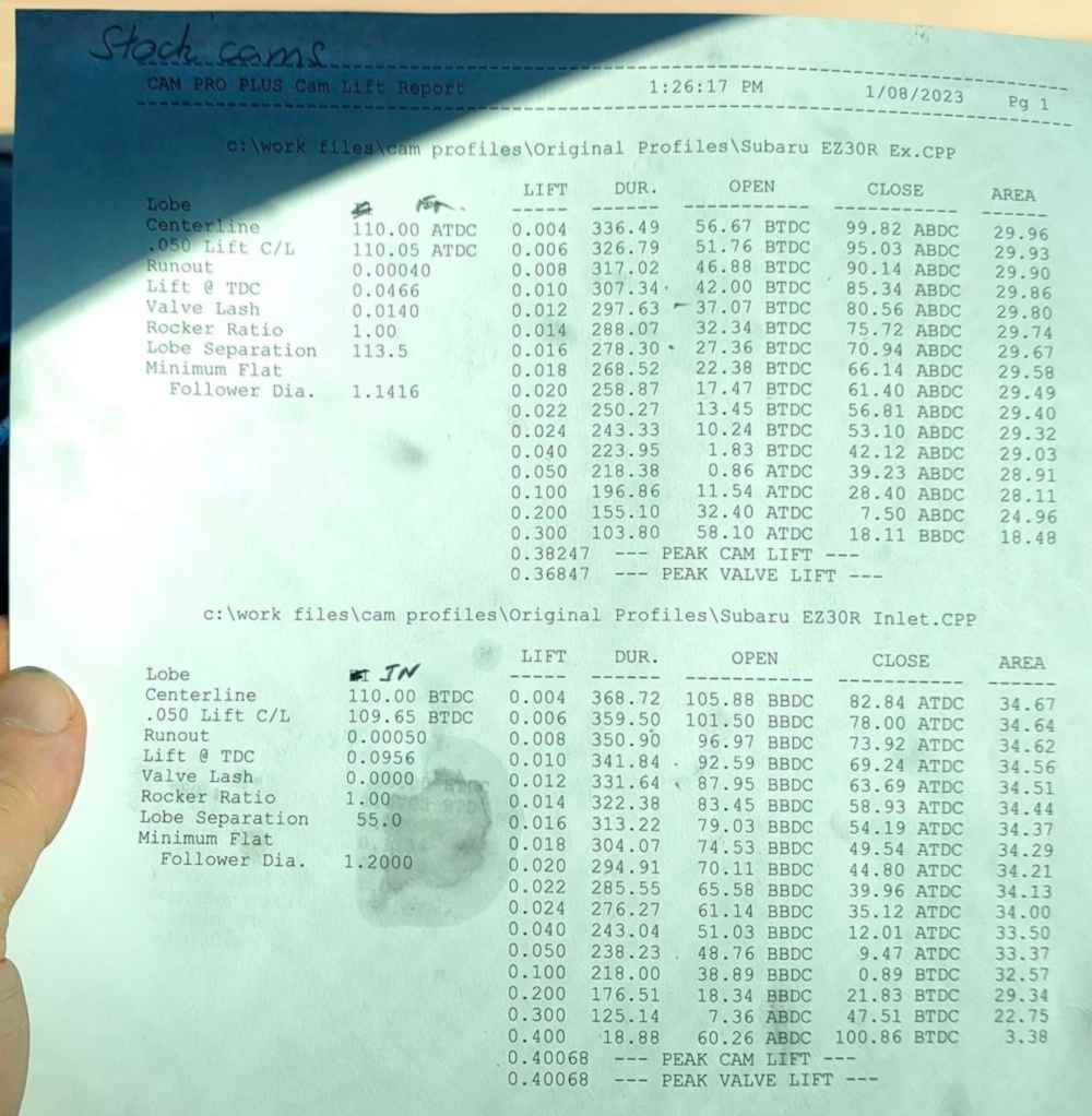
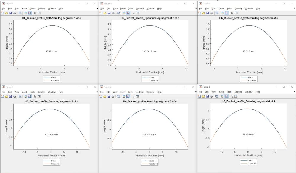
MEASUREMENT METHOD The cams were mounted in a lathe with a 2000 point optical encoder attached to the back of the headstock. A digital indicator with micron accuracy was mounted to the carriage as rigidly as possible. The encoder and the digital indicator were then logged against time, data transfer being achieved via RS232 serial. The indicator outputs its screen reading in its own format at roughly 10Hz, and the encoder at around 50Hz in plain ASCII. Measurements were then merged with respect to time after the measurement was completed. Using the one PC to log both data streams ensured that data timestamps are not offset. The cam was rotated as slowly as possible, approx 1.5 RPM. A number of rotations were logged and averaged together to improve signal to noise. The measurements were taken with a flat face follower. This has a number of advantages: 1) The inlet cams for the EZ30D and EJ255 engines as well as all exhaust cams fun using flat faced buckets, so no transformation needs to occur to get actual valve motion 2) Side loads on the dial indicator is minimized. This minimizes friction and deflection in the measurement setup 3) The measurement is (theoretically) unaffected by an offset between the centreline of the indicator and the centreline of the cam. This removes one source of inaccuracy and makes setup easier. The indicator only needs to be roughly in line with the cam The main disadvantage is that a flat follower cannot be used on a cam with concave sections, ie undercut. This is not a problem for the EZ30R cams, as using the reflection of a point light source against the ground surface while the cam is rotated shows that all sections of the cam are convex. Therefore a flat faced follower can be used, despite the engine using curved buckets. The curvature of the EZ30R bucket was estimated by mounting the bucket in a milling machine and dragging an indicator across the follower surface. Two micron accuracy indicators were used for this giving XY coordinates that an arc could be fitted to with least squares. I did this a long time ago, and do not have images. THE MATHS To transform the measured flat follower motion to that of a translating roller follower, the lobe profile needs to be calculated and then a geometric offset applied equal to the radius of the follower. The lift for a given angle of cam rotation is then simply r – base circle diameter/2 - roller radius when converted to polar coordinates. I wrote quite a bit of MATLAB code to perform the data merging, measurement delay estimation, de-glitching, runout correction, smoothing, lobe generation and follower correction. This is the best explanation of flat face follower kinematics that I’ve found to date. Props Dr Starr. This is the foundation for generating the lobe profile from the flat face follower lift coordinates http://www.me.unm.edu/~starr/teaching/me314/camprofile.pdf The dependency of the cam profile on the derivative of the lift measurement makes noise rejection / smoothing very important. Derivatives greatly amplify noise, and if too much noise is present the lobe curve begins to self intersect. Smoothing however rounds off features like the ramp transitions, so there is a balance. Obtaining low noise measurements in the first place gives the best chance of getting a clean lobe profile with an acceptably low amount of smoothing. Other considerations: 1) Run out correction. With no run out, the measurement of the base circle should be constant. If there is run out, the measurement will be a sinusoid at the frequency of once per revolution. To correct for run out, fit a sine curve,, to the measurement of the base circle and subtract it from the entire measurement. 2) The indicators have a small delay between taking a measurement and beginning a transmission of the reading, which when merged with the encoder measurement with respect to time, leads to noise in the measurement. The arduino begins transmitting the encoder reading almost instantly. By experimentally adjusting the time offset over a long measurement to minimise noise, the delay in the indicators was estimated to be around 22ms.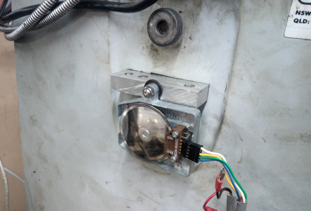
-
EZ30R AVLS Cam Specs deep dive
donkeytits1 replied to donkeytits1's topic in NA Fuel Injection Engine Tech
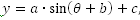
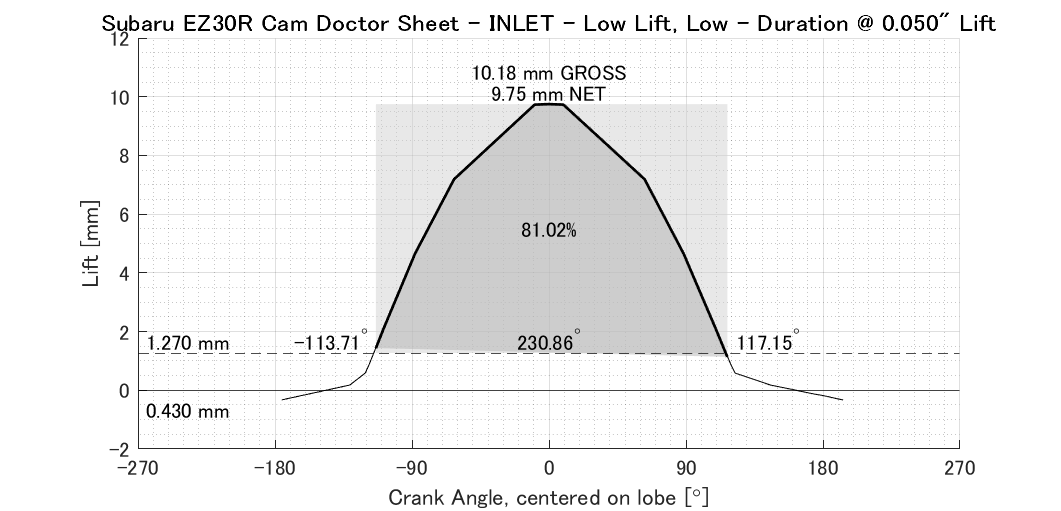
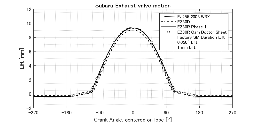
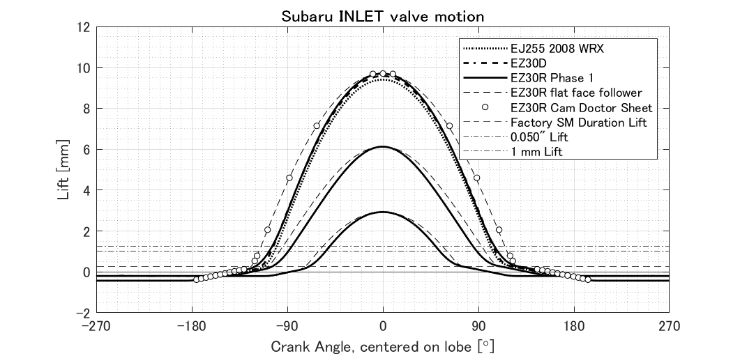
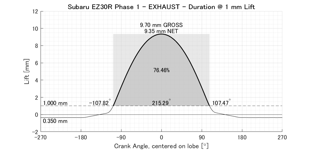
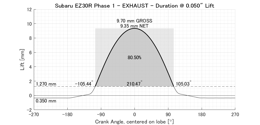
CAM DOCTOR SHEET There have been a cam measurement sheets getting around. The example posed is from a H6 facebook group. It is unclear from the text what follower shape was used for measurement, but the duration specs seem suspiciously large. Plotting this data over the top of the corrected results, it is clear that the Cam Doctor measurement was taken with a flat follower and that no correction for the curved ALVS follower was applied. This exaggerates the measured duration of the cam. In reality, the EZ30R has remarkably similar cam design to the preceding EZ30D and the EJ255 The 'CAM Doctor' Exhaust Measurement seems accurate.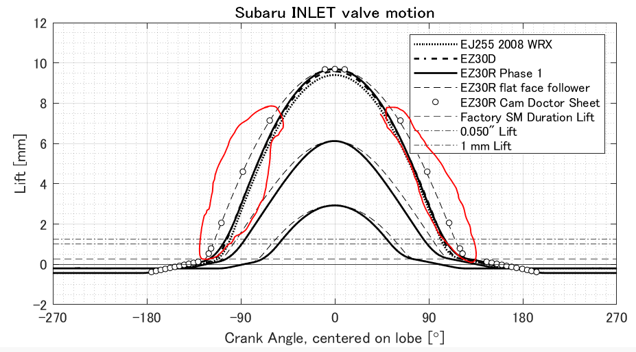
-
EZ30R AVLS Cam Specs deep dive
donkeytits1 replied to donkeytits1's topic in NA Fuel Injection Engine Tech
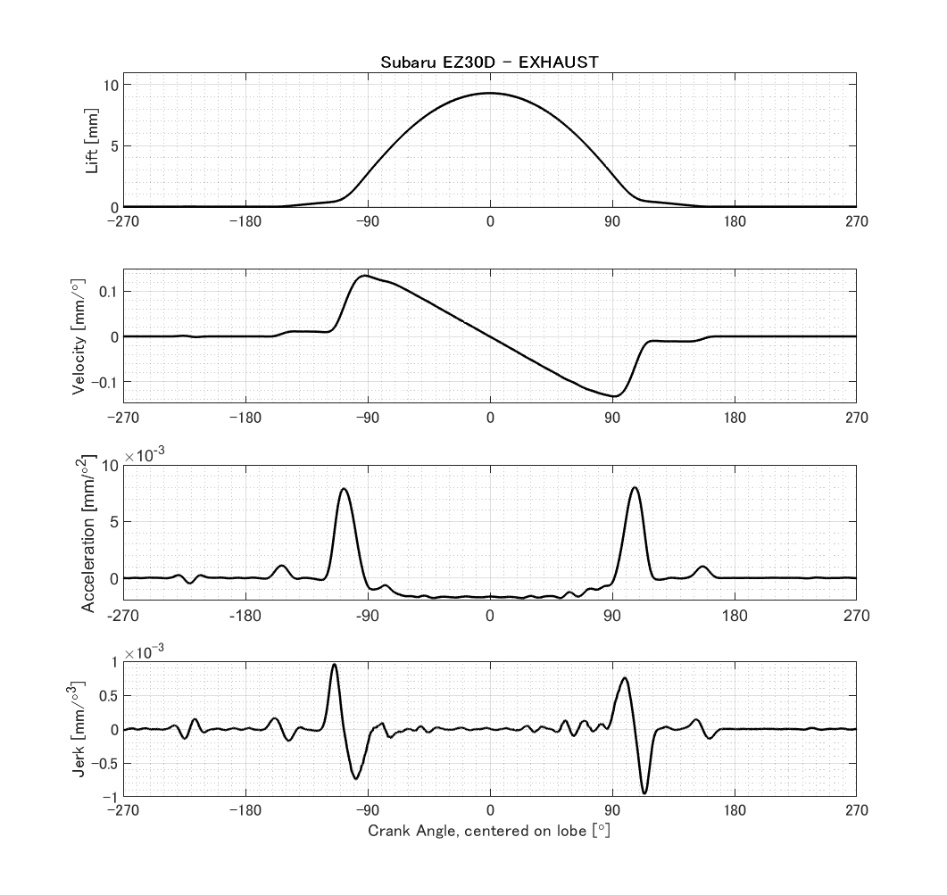
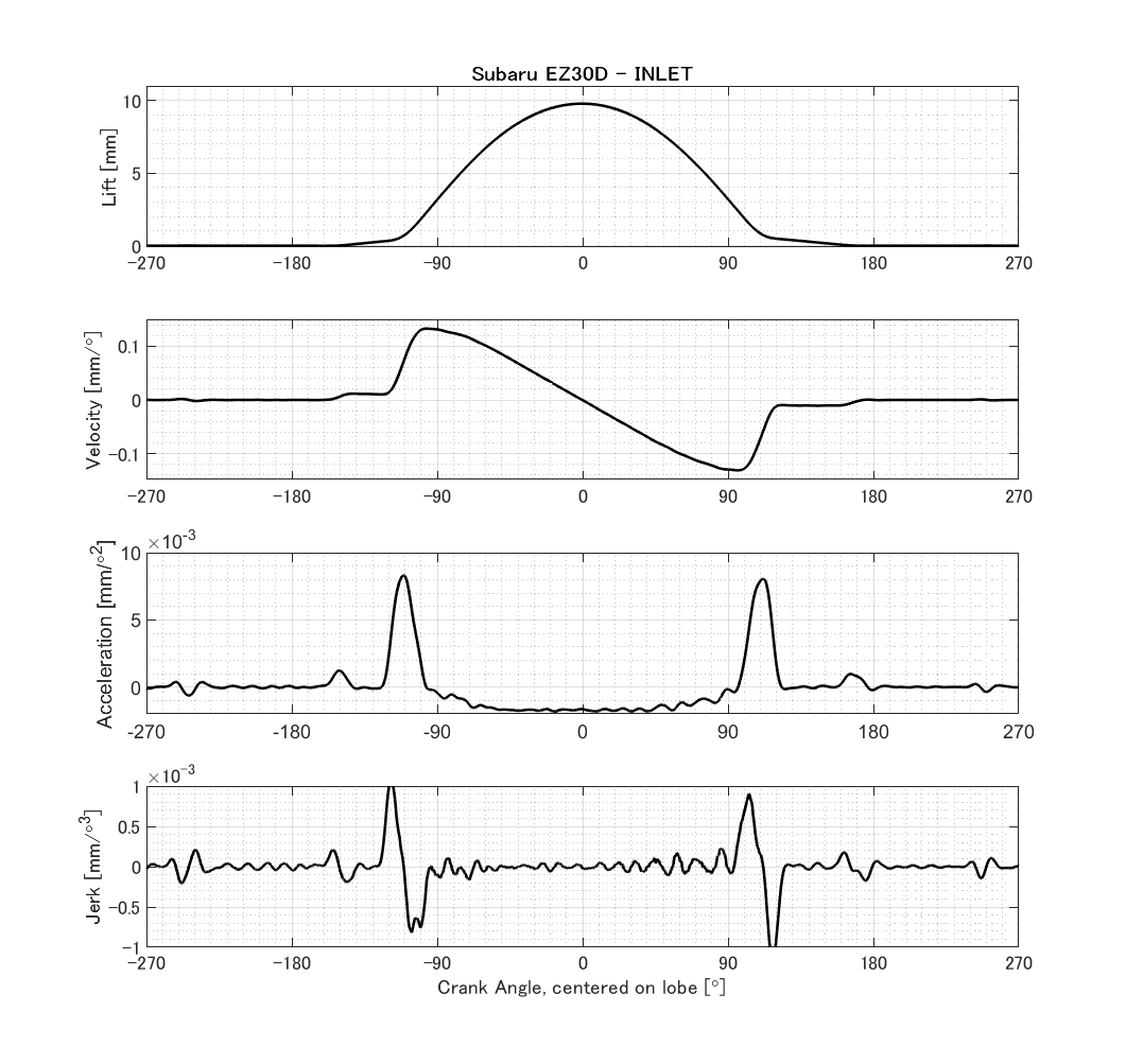
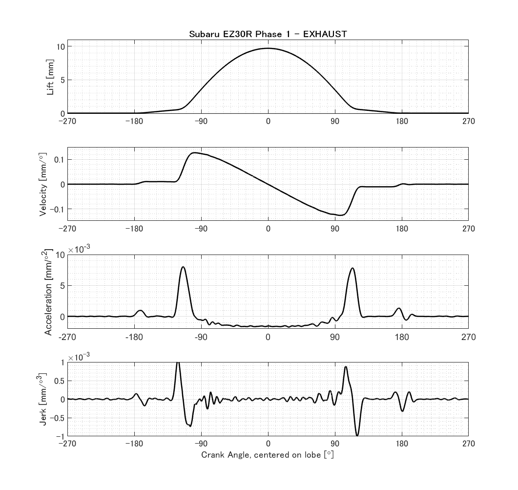
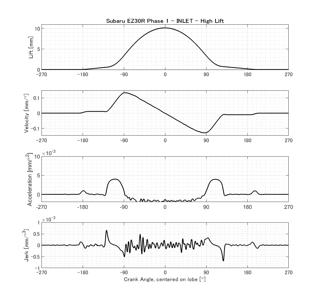
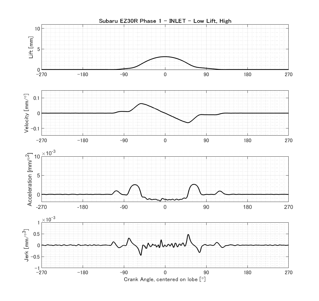
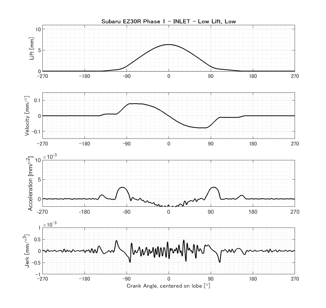
VELOCITY AND ACCELERATION PROFILES The measurements were detailed enough to give reasonable insight into the higher derivatives. The EZ30R cams appear to be less aggressive in terms of peak acceleration. Peak negative acceleration is the biggest determinant for required valve spring rate, along with valve train mass. It can be seen that all three engines are quite similar.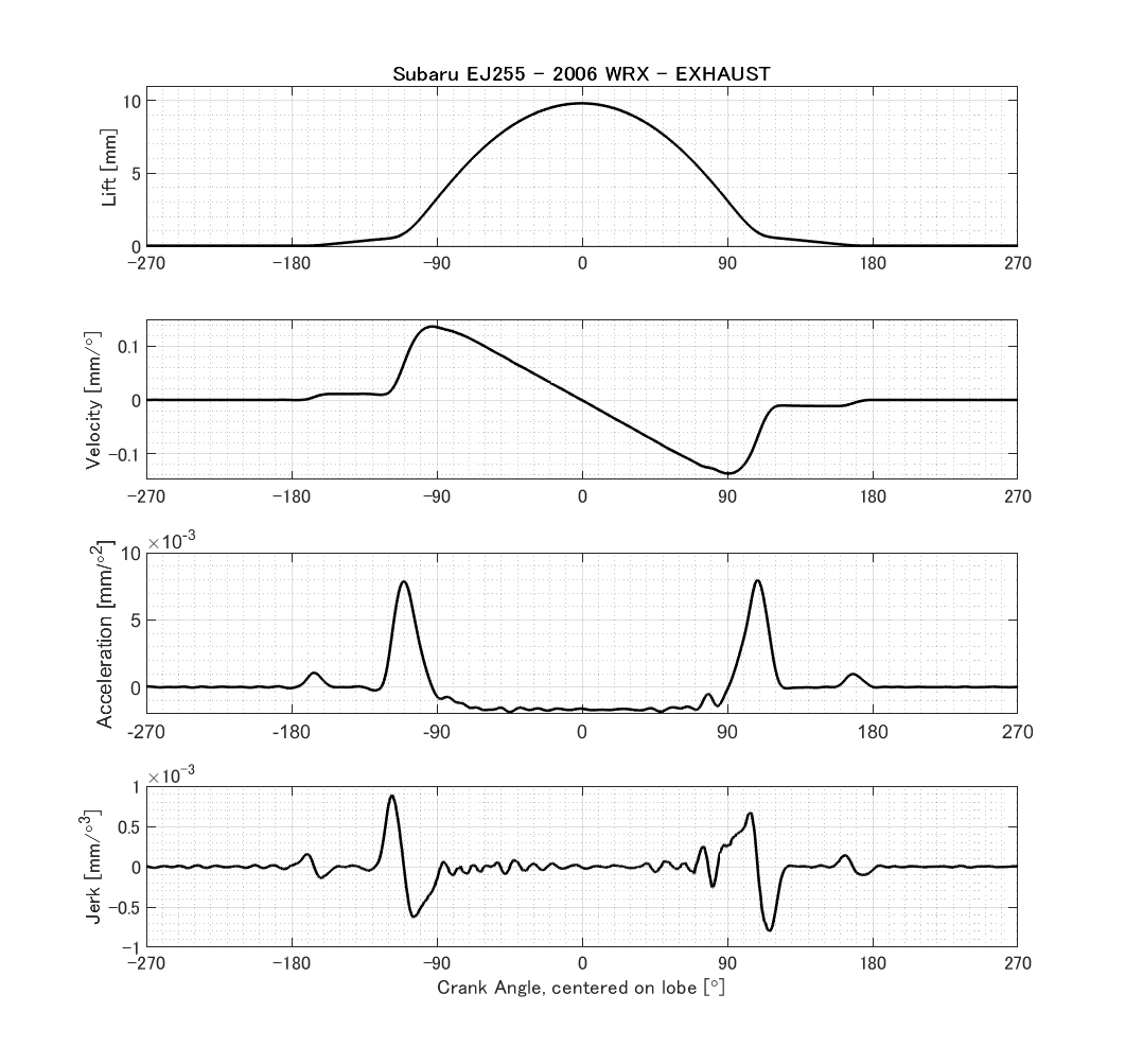
-
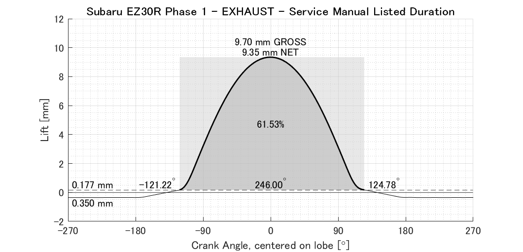
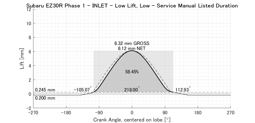
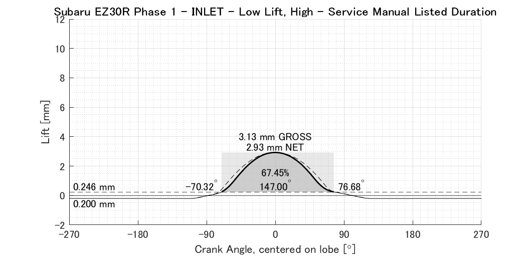
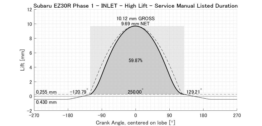
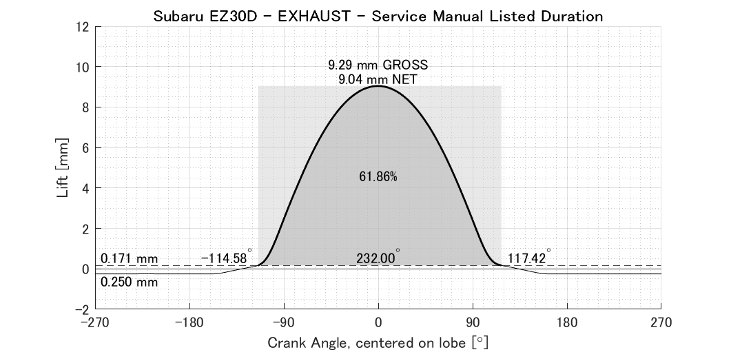
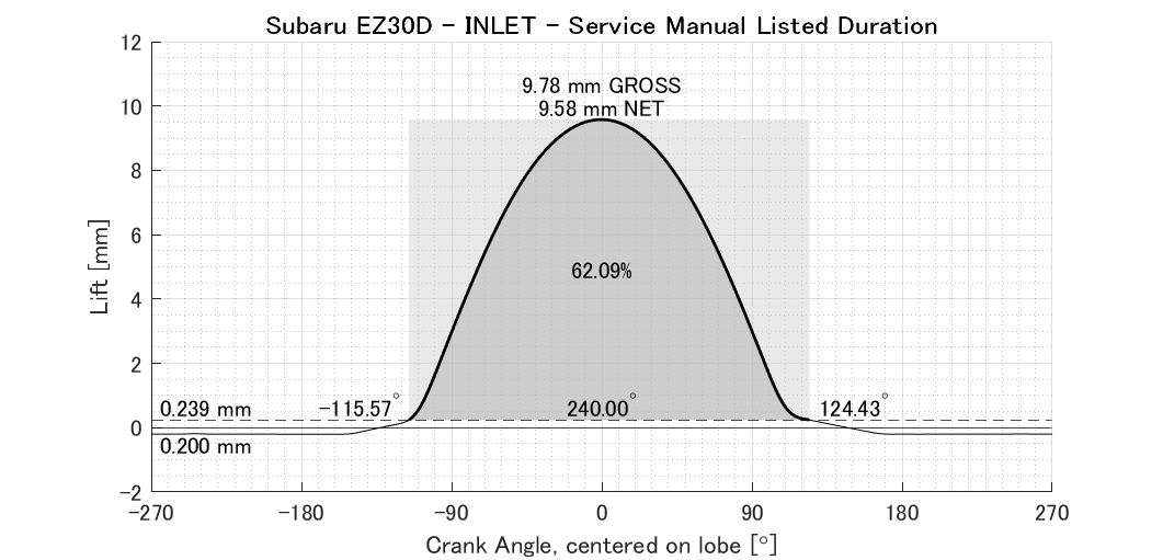
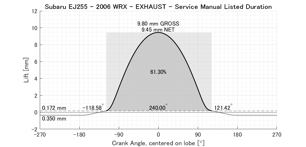
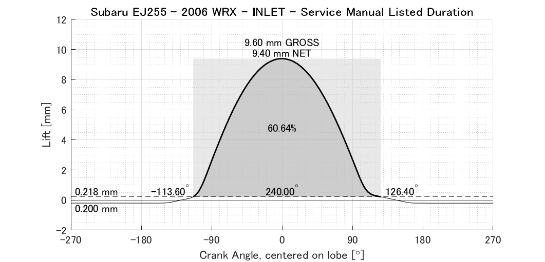
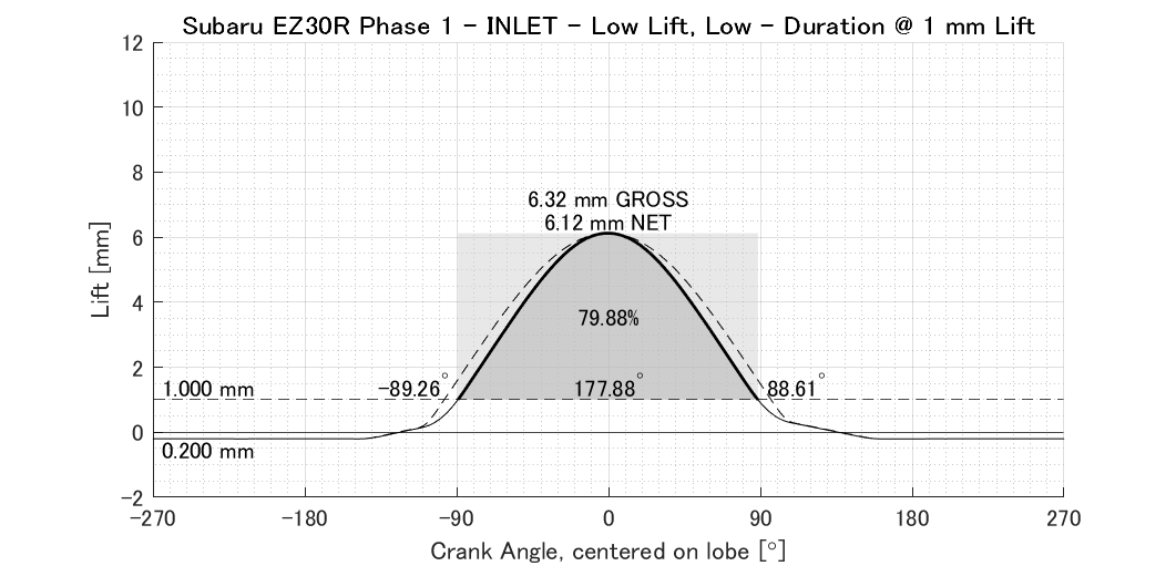
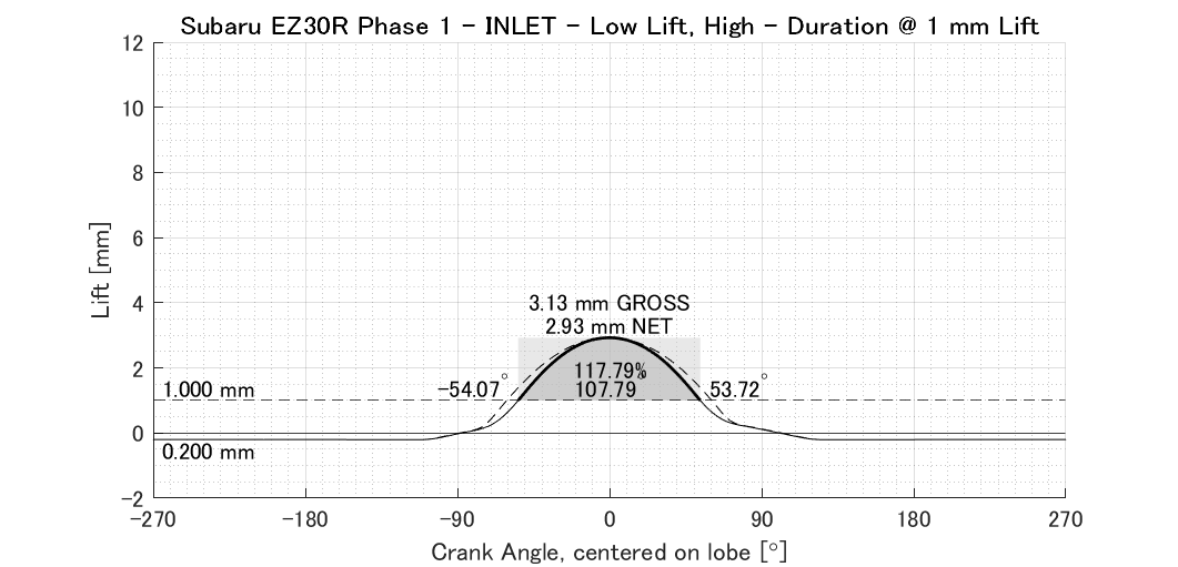
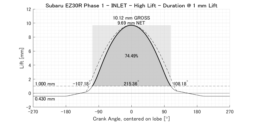
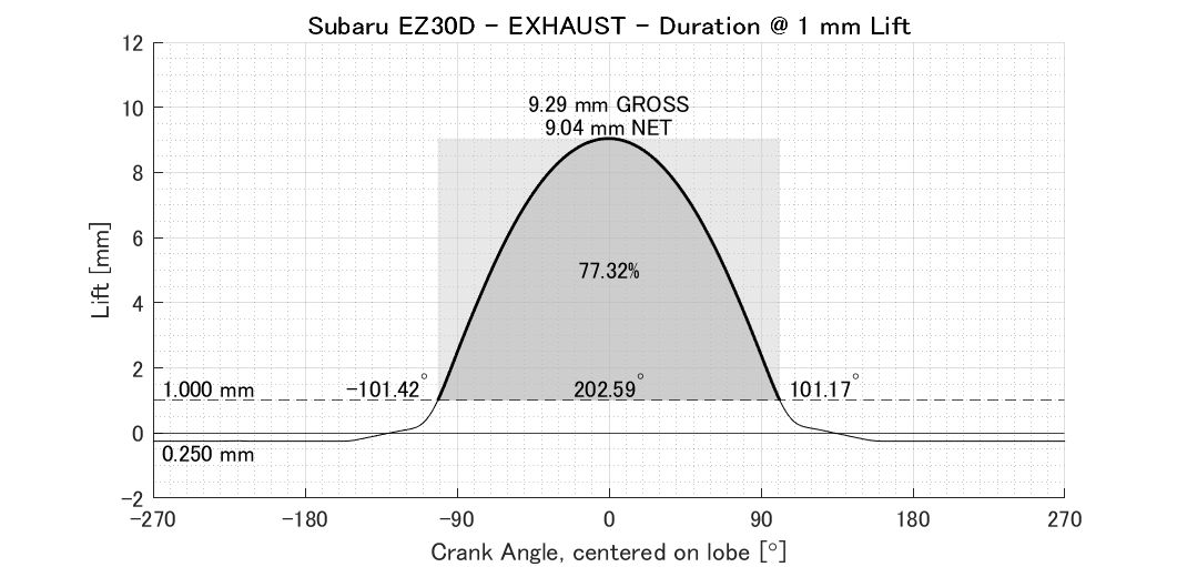
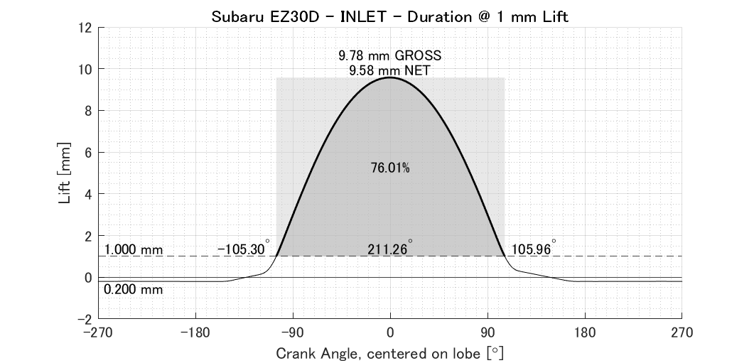
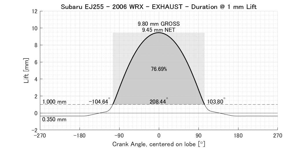
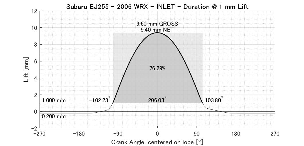
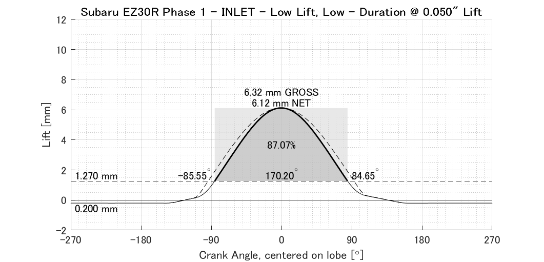
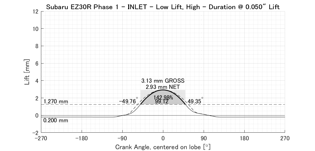
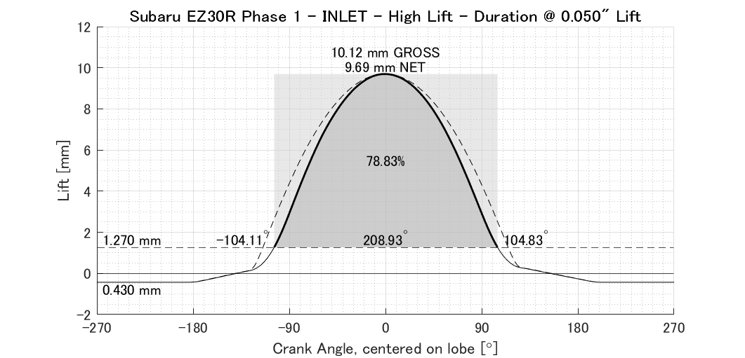
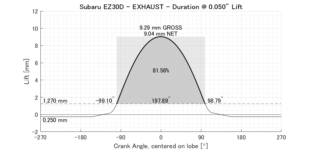
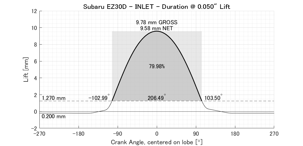
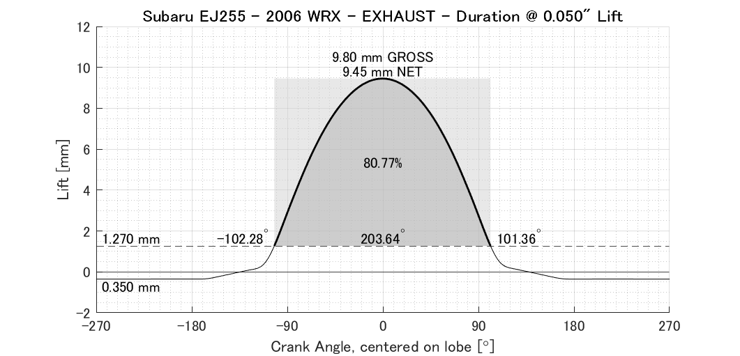
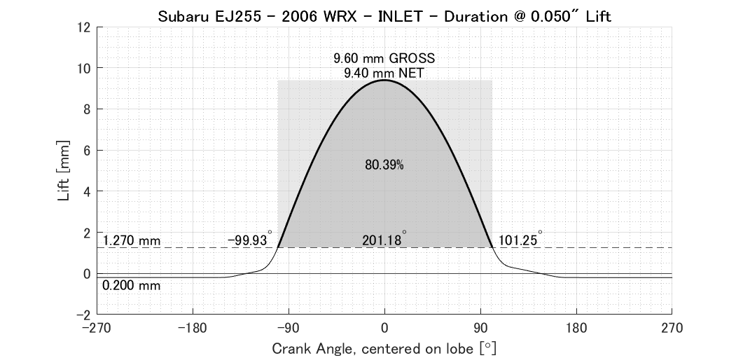
Having an EZ30D in my car, and knowing the EZ30R has an extra 20kW I’ve always been interested in the cam specs of that engine. I have seen a couple of numbers thrown around over the years, and they have always seemed a bit exaggerated. I became especially interested after having a head apart and seeing the interesting follower arrangement the AVLS system uses. I got the cams from those heads, and finally I have had the opportunity to measure them. I have also measured the bucket profile and derived the real valve motion. I have also measured the cams for an EZ30D and an EJ255 WRX (2006) for a comparison. MEASUREMENTS Engine Cam Clearance Gross Lift Net Lift Factory Spec At 1 mm Lift At 0.050" Lift Open Close Duration At Lift Open Close Duration Open Close Duration EJ255 Inlet 0.20 9.60 9.40 5 BTDC 55 ABDC 240 0.218 -102.23 103.80 206.03 -99.93 101.25 201.18 Exhaust 0.35 9.80 9.45 55 BBDC 5 ATDC 240 0.172 -104.64 103.80 208.44 -102.28 101.36 203.64 EZ30D Inlet 0.20 9.78 9.58 5 BTDC 55 ABDC 240 0.239 -105.30 105.96 211.26 -102.99 103.50 206.49 Exhaust 0.25 9.29 9.04 52 BBDC 0 ATDC 232 0.171 -101.42 101.17 202.59 -99.10 98.79 197.89 EZ30R Inlet HL 0.43 10.12 9.69 22 BTDC 48 ABDC 250 0.255 -107.18 108.18 215.36 -104.11 104.83 208.93 Inlet LL L 0.20 3.13 2.93 N/A N/A 147 0.246 -54.07 53.72 107.79 -49.76 49.35 99.12 Inlet LL H 0.20 6.32 6.12 N/A N/A 218 0.245 -89.26 88.61 177.88 -85.55 84.65 170.20 Exhaust 0.35 9.70 9.35 60 BBDC 6 ATDC 246 0.177 -107.82 107.47 215.29 -105.44 105.03 210.47 AVLS https://commons.wikimedia.org/wiki/File:Switching_tappet_for_SUBARU_EZ30_(INA).jpg The AVLS system in the EZ30R engine is a direct acting system with an innovative concentric split follower. For each valve there are a set out outer high lift lobes and an inner low lift lobe on the cam shaft. The inner lobe runs on the inner section of the follower and the high lift lobes run on the outer section of the follower. The inner section of the fowler acts directly on the valve stem and when not engaged the outer section is free to slide along the axis of the valve. Therefore by default the valve follows the low lift lobe. When activated, oil pressure moves a pin across that locks the outer section of the follower to the inner section and the valve then follows the high lift profile. The follower has curved surface, with the flat axis parallel to the cam centreline. The cross section of the surface is an arc, and there is a different radius used for the inner and outer sections. The inner section was measured to have a 43mm radius and the outer section was measured to have a 52mm radius. The inner section of the follower protrudes slightly. The lobes seem like they have a slightly different base circle diameter as well. 32mm vs 32.5mm. To measure valve motion for the EZ30R ALVS lobes a flat follower was used and then a correction was applied to account for the curved follower. SERVICE MANUAL SPECIFIED DURATION The valve timing specifications given in the service manuals appear to be with respect to the corners of the profile ramps. The ramps end at very low lift levels and so in a practical sense, the factory open and close angles can be described as the start and end of any visible movement. In terms of specifying the factory specs in terms of a check lift, the non symmetrical size of the ramps makes it a little misleading. The lead-out ramp is longer that the take-up ramp. None the less, the check lift for intake cams appears to be around 0.25mm and the exhaust cams 0.17mm. The lower peak acceleration of the EZ30R cams (discussed later) also seem to exaggerate the duration in the service manual. SPECIFICATIONS AT 1mm LIFT Aftermarket cams tend to spec cam duration at 0.050” or 1mm, which is when the valve is or close to being accelerated to its maximum velocity and hence is not affected by the ramps or the aggressiveness of the initial acceleration events. It is easier to compare camshafts using this measurement, hence why they are used for aftermarket cams SPECIFICATIONS AT 0.050" LIFT
(1).jpg.2d56451ddbf43badf87f911ef035cb4a.jpg)
-
donkeytits1 changed their profile photo
-
Yeah, that's one of the cleanest ones I've seen... my daily driver has enough rust that the front of the rocker moves independently of the back of the rocker if I open my door into the stop...
-

EA82 spark timing puzzle
bushytails replied to el_freddo's topic in Old Gen.: 80's GL/DL/XT/Loyales...
So you tested it and found the timing does not advance with increasing engine rpm? It's probably just stuck, and needs penetrating oil and poking at until it frees up. -
Reason for a Melted Distributor Rotor?
bushytails replied to LaMamelle's topic in Old Gen.: 80's GL/DL/XT/Loyales...
Kinda hard to tell much from those pics... But it doesn't matter much anyway. You're going to need to inspect the distributor. Shaft wobbles so much the rotor is hitting things? Time for bushings. Some part of the advance mechanism loose and jamming into the rotor? Repair. Etc. Find nothing wrong? Put in a new rotor and inspect periodically. -
2.2 OBD2 swap into ‘85 Brat
bushytails replied to Greentractorfarmer's topic in Old Gen.: 80's GL/DL/XT/Loyales...
I'm having a hard time understanding your post. You're using the same engine and harness and ecu that you used in the rolled car, in the new car, but now it bucks? Or this is an entirely new swap? If it's all the same parts that worked before, it's obviously not incompatibilities between them or what the wiring harness supports. Or did you mismatch intakes when you originally built? Again, if it worked before, not the problem now. Since you're suspicious of the fuel supply, start with a mechanical fuel pressure gauge. Extend the hose long enough to route out through the edge of the hood and tuck under your windshield wiper. Take it for a test drive. Fuel pressure should be solid, and should go up 12 psi when you go from idle to full throttle. Does it buck at idle, or only above a certain amount of engine load? On your obdii scanner, use the live data mode (if it doesn't have live data, bin it and spend $50 on a new one), looking for any sensors that move in a sudden fashion, especially if it correlates with the bucking. If it's a fuel injection issue, an oscilloscope is really handy... Here's a couple pics from last time I was troubleshooting a bucking issue: https://imgur.com/a/RwWTdwG In these images, the jumpy green trace confirmed the bad component - MAF sensor. -
Hi All, I’ve been learning from this wonderful site for half-dozen years, so let me start my first post with a hand-clapping thanks to the many people who’ve helped me along. I bought an ‘83 GL new, kept it all these years, and in 2021, swapped in a 2000 Impreza 2.2, California spec. My fun with that wagon ended with a roll-over, last year. I’m lucky to have found a running Brat (1985) and began pulling over the parts from the wagon, which included the 15” wheels and 2.2 fuel injected engine, wiring harness, and pretty much all the interior fittings. Now to the point of this post. I am unable to make the engine run in the Brat as it did in the wagon. The engine starts, idles smoothly, and can have full power. But intermittently. The stutter/cut-out is throughout the whole range of throttle, and depending on the rpm, can best be called ‘bucking’. The fuel system in the donor car had an in-tank pump with sensors for fuel level, pressure, temperature, and control valves for drain and purge (not the purge valve at the fuel rail). None of the sensors and valves came over to the Old Gen cars, although I did preserve the sensor wires to the area of the ECU. I ran a 5/16” line from an external Ford fuel pump to supply the engine, and used the original 1/4” supply as a return, and the 3/16” as a vapor line from engine to tank. That worked fine on the wagon, but I suspect the current problem is related to this set-up. I’ve replaced a lot of the sensors: front O2 at the exhaust, knock, throttle position, engine block temp, crank sensor, and tested the purge control valve to be operational with voltage, also the ECU with another. Also new plugs when moving the engine to the Brat, and then a new coil. The plug wires were new 5,000 miles ago, so don’t think the problem is in the ignition. I realize this is a vague description of what is in place right now, and hope someone will be interested and start a conversation to help with the next step. I’m wondering if anyone has opinion/experience with the Cali-spec engine and whether my wiring loom can support an older (Gen1) intake and its ECU. I’m feeling pretty desperate and leaning toward finding a mechanic willing to work on this swapped set-up, with the thought that a more sophisticated diagnosing kit could narrow down the issue, whether the ignition or fuel is quitting. I’m working with a simple OBD reader, multimeter, pin-out chart for the ECU, and a 72- year old brain. It’s tough. Thanks for your time.
-
EA82 spark timing puzzle
el_freddo replied to el_freddo's topic in Old Gen.: 80's GL/DL/XT/Loyales...
Hey bushytails, Thanks for that mini procedure for an easy check of the mechanical/centrifugal advance. I might have a tinker if I get the chance before it disappears. I don’t think the fuel mixture is rich as I changed the carb due to an idle issue. The replacement stock hitachi was known to run well and I haven’t seen anything different than expected. No black smoke indicating running a rich mixture and no running on that’s common with a rich mixture and engine shut down. Thanks for all of your thoughts on this. I think it can safely be put down to an issue with the mechanical/centrifugal advance. It’s interesting that it runs so well with static timing set at 20° BTDC. Cheers Bennie - Yesterday
-
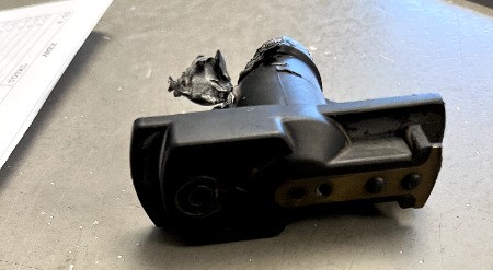
 Howdy all, I have my 88 GL in the shop getting its engine resealed. I got an update from them an apparently the distributor rotor had melted in the distributor, or potentially tore it somehow? It wasn't melted/torn at the head, but at the base of the rotor head. Luckily it turns out I have an extra, however would anyone know why something like this would have happened? It was an older part, and I don't when it was last replaced, so it could be that it was just on the way out anyways. I hadn't had any issues with anything ignition or engine electrical before. I'm a bit worried that they're going to put the replacement in and the same thing might happen, it not immediately, maybe a few 100 miles down the freeway. Attached are some photos of the damage the shop sent to me. Any wisdom would be appreciated. Thank you! -Philly
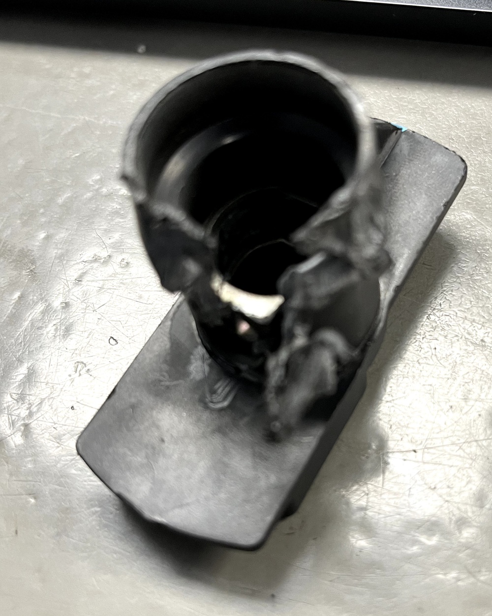
-
From what I can see, that car looks surprisingly solid. Nice find!
-
 Have you taken this thing to a muffler shop and let them take a look at it? They’re probably going to be in the position to tell you what’s going on.
 -
The Awesome Older Generation Picture Thread
LaMamelle replied to 6 Star's topic in Old Gen.: 80's GL/DL/XT/Loyales...
First post! Here are some pics of my 88' GL. I call her Constance. I have just about a million photos of her, but these are some of my favorites. Everything is stock except the exhaust which custom made by the last owner, nothing loud just not stock. Not exactly sure why it was done but it's not an issue, so I don't mind. Also, the rims were painted black which I'm a huge fan of. -Philly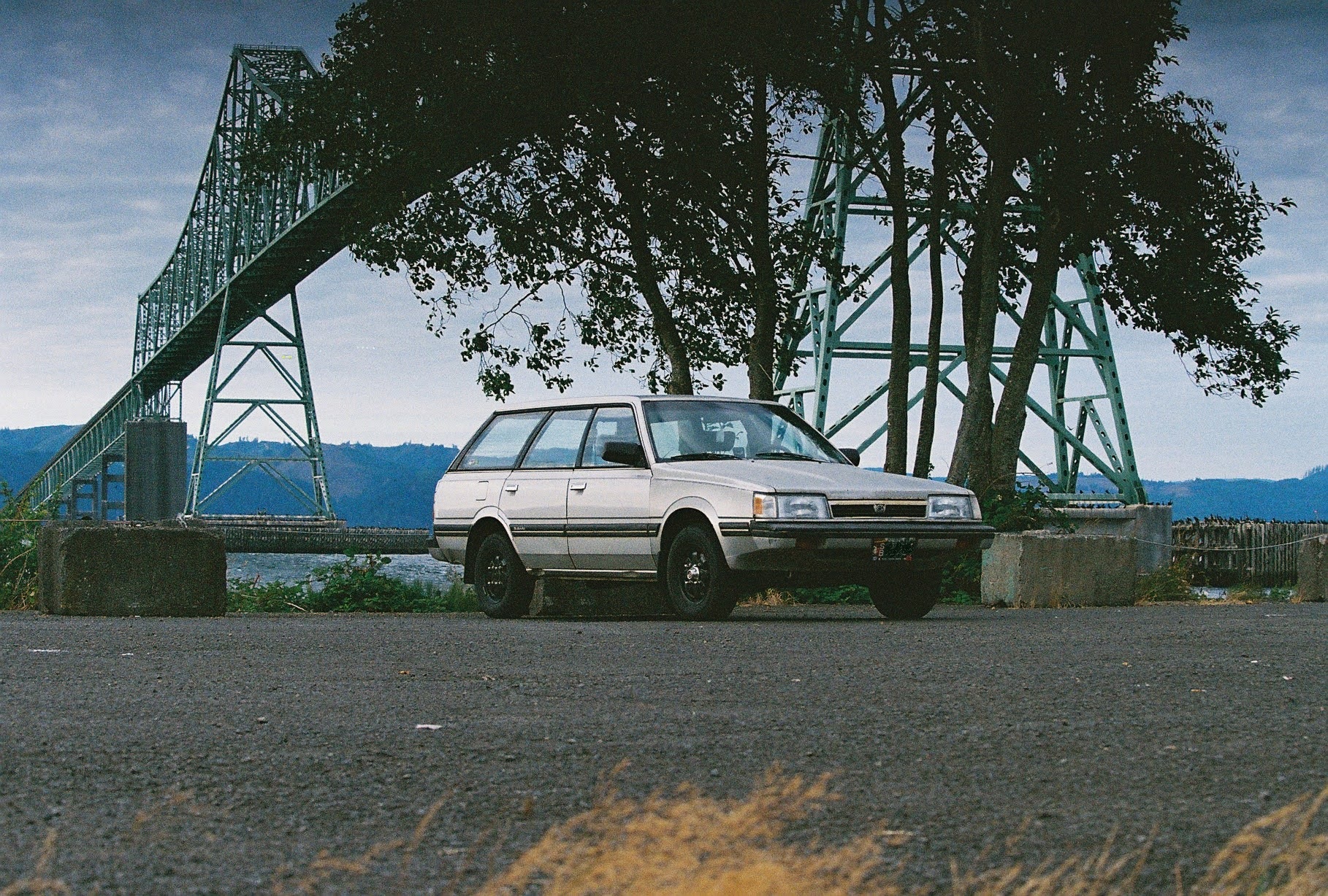


-

long travel Outbacks or making Subarus faster and more reliable offroad
slammo replied to pontoontodd's topic in Off Road
Oh wow, didn't foresee that issue with brake-to-strut clearance! Would be interested to see another angle of that. -
EA82 spark timing puzzle
bushytails replied to el_freddo's topic in Old Gen.: 80's GL/DL/XT/Loyales...
Yes, the weights and such are the mechanical advance. With the vacuum advance disconnected, slowly rev the engine up. The timing should advance proportional to engine rpm, to about 3000rpm or so. I don't have an advance curve for the ea82 handy, but it should just smoothly increase with rpm until it reaches a limit around 2-3k. Another possibility is your mixture is way rich, and you're hiding it with timing. Overly rich mixtures burn slower and need some extra timing to compensate. -
EA82 spark timing puzzle
el_freddo replied to el_freddo's topic in Old Gen.: 80's GL/DL/XT/Loyales...
Vacuum advance works - tested with a hand vacuum pump watching the mechanism in the dizzy and the same when at idle. Timing done at idle with the vac advance disconnected and plugged. Idles well at 8° or 20° of timing. Just completely gutless when set at 8°, slowly pulls up the revs when past 3000rpm with the foot flat to the floor. When doing the same with timing at 20° it will happily keep pulling hard well beyond 4500rpm - and runs the way you’d expect it to. No vacuum leaks, checked over all of these and replaced several hoses as a result of vacuum leakage. It doesn’t ping or run hot. One thought I had was the centrifugal weights have an issue and it’s running purely off the vacuum advance - and the timing set at 20° counteracts the lack of centrifugal advance. Thanks for your thoughts on this fellas. Cheers Bennie -
Thanks man, I really appreciate it! Yes, it's 2WD 5MT. I'm going on vacation tomorrow for a week so I'm going to have to tackle it when I get back. I wanted to do more testing before I dropped ~$100 on one of those resistors and the one I have now definitely looks to have been replaced. Good call on the radiator.