Search the Community
Showing results for tags 'cam'.
Found 7 results
-
Replacing the head gaskets on my 92 Loyale. Engine is removed, stripped down, cylinders are removed and on the work bench. A couple of questions as I progress....... 1. On the cam tower I have read to ensure the use of the metal reinforced O'rings on the cam tower (P/N 13089AA010). Is it just one O'ring per tower? 2. Looking at the Miles Fox video (#21) it shows a large O'ring for the whole cam tower being covered with Permatex grey. Is that O'ring purchased or made? Special material? 3. Are the alignment pins on the cylinders and block removable? Removing them would make it easier to clean the surfaces for the new head gasket. Should I remove them? Suggested technique for removal? 4. Seven Hydraulic Lash Adjusters (HLA's) spin freely by hand, while one is different (spins real hard, sticky, feels like metal to metal contact when it is turned). Seems like it needs replaced. Suggested technique for removal of this Hydraulic Lash Adjuster (HLA)? Can I replace just one? Happy Independence Day! Bill
-
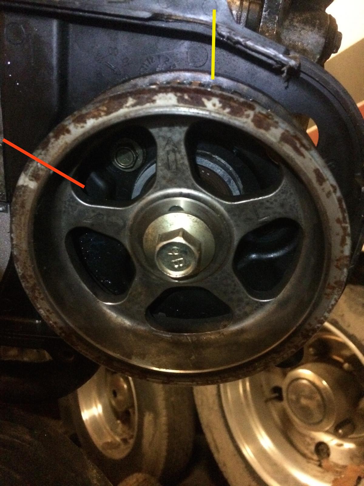
 Hey guys, I just pulled the engine and did the head gaskets on my EJ251 legacy wagon. As I was about to install my new timing belt, I realized that I am entirely unable to get the left side cam sprocket timing marks to line up! The repair manual and multiple internet resources show that the mark should be going pretty much straight up towards a notch in the rear timing cover. My cover happens to be chipped, but I can see where the notch used to be. For some reason, the cam sprocket just won't stay where it *should* be, the tension whips the cam far to either side of it (YES, my crank timing mark is lined up properly, all pistons are recessed, I didn't just destroy my valves). These are the closest places to the timing mark that the cam will rest. Timing hash on cam is indicated with red line. Timing mark on timing cover is indicated with a yellow line. What is going on here?? I have read on multiple articles AND the manual that there should be no tension on cam when it is at proper point, this isn't some weird Audi that I should need special clamps for. Thanks for the help!
-
 I have a 2008 impreza, 2.5i, SOHC. I just replaced the blown motor with a used motor with 60,000 miles on it. Replaced all the timing components except for the cam gears. When I tried to start the car, the motor wouldn't turn on it's own. From what I've been told, the camshaft position sensor communicates with the raised bars on the back of the left side cam gear which come in 2 bar, and 7 bar varieties. My question is, how do you tell what kind of cam gear you need for the car to start? I don't have the original motor anymore as it was turned in for a core refund after we transferred over all of the accessories. Any other applicable advice is welcome and I can provide more info about the car as needed. Thanks in advance! - Bryan
 -
 All: So I got the motor pulled yesterday!!! Thanks to everyone for all the help and great threads. Now the adventure begins. Clutch, oil sep plate, cam seals all on the list. I cannot find any thread on how to replace the drivers side rear cam seal. Anyone have any advice? Part numbers? 1995 Subaru Legacy L. EJ22. Not sure if leaking...or just spray from the valve cover leak...but planning to replace as many seals as I can while I have the motor out. Thanks, Tom
 -
 I'm new to this board, but I'm on several other ones. I need to know the answers to this problem quickly, please help! I'm doing the head gaskets on my 1998 Legacy Outback EJ25 DOHC. I've rounded off several of the cam cap bolts on the passenger side head because the metal is very soft. 1. How can I remove these bolts without getting metal shavings in my head? 2. What can I do to prevent having the same problem on the other head? Thanks in advance.
 -
 Hi Any help would be much appreciated. I have been trying to get this car going again. I have a 87 Subaru GL 1.8L ea82 carburetor engine Manual Transmission. I am doing a timing belt replacement. Plus, I decided to change the cam and crank seals at the same time. I was following the basic Chiltons book while doing the change. I removed the old belt in the initial part of the change. Now as I am putting things back on, and ready to put on the new timing belt, I am reading to have the cam sprockets positioned differently then they are. On the Driver side my Cam sprocket is DOWN. On the Passenger side my Cam sprocket is UP. Now that I have the timing belts off, how do I move my cams to the proper position to finish belt install? I'm nervous about how they should be correctly moved, all instructions simply say line it up with no in-depth details on how. Here is the DRIVER CAM with hole DOWN: http://s12.photobucket.com/user/luckyme218/media/car/photo1.jpg.html Here is the PASSENGER CAM with hole UP: http://s12.photobucket.com/user/luckyme218/media/car/passcam.jpg.html
 -
I think I am almost there to getting this 1992 Loyale back up and running. I had diagnosed this engine as a broken timing belt and it was. The Driver side belt was majorly broken. However, I got the new belts on and the timing seemed to be weird and I can't get it to fire up. The pass. sides seems like it is firing but the driver side is not. It's getting spark and fuel and compression. but no combustion. Per Chiltons guide I lined up the dots to the top of the timing backing and the crank sproket dot up as well. but the driver side 2/4 is fouled by fuel, well cylinder 2 is. I didn't check c4. Compression is abour 150 psi and holds. (no leakage) Chilton siad something about applying pressure while setting the timing belt, but if I did that then it would not be on it's mark. So is there anyone out there that has done this repair and knows the exact thing to do to make sure this thing is in time? I've made sure that the engine was at TDC beore I aligned the cams. Thanks for your assistance! -Mike