DaveT
Members
-
Joined
-
Last visited
Everything posted by DaveT
-
From memory.... pretty sure they are 14mm hex heads. 10mm diameter. 1.25mm pitch. Lower nut on the starter was 17mm hex iirc. Other nuts were washer face or used with washers and split locks.
-
-
-
-
Bubbled paint rust is worse than you might think. It's coming through from behind. You will be doing yourself a big favor to find a Factory Service Manual for whatever model & year you end up buying. All those details of what's missing or just an option the car doesn't have are in there. Of course, no harm in asking here either, it just helps a lot to have the info on hand.
-
-
DaveT replied to idosubaru's topic in 1990 to Present Legacy, Impreza, Outback, Forester, Baja, WRX&WrxSTI, SVXI've been using that. They also have a copper version now, I have been using. Not long enough to have long term idea yet. I've also used synthetic wheel bearing grease / GL2 and that stays around for a long time too.
-
-
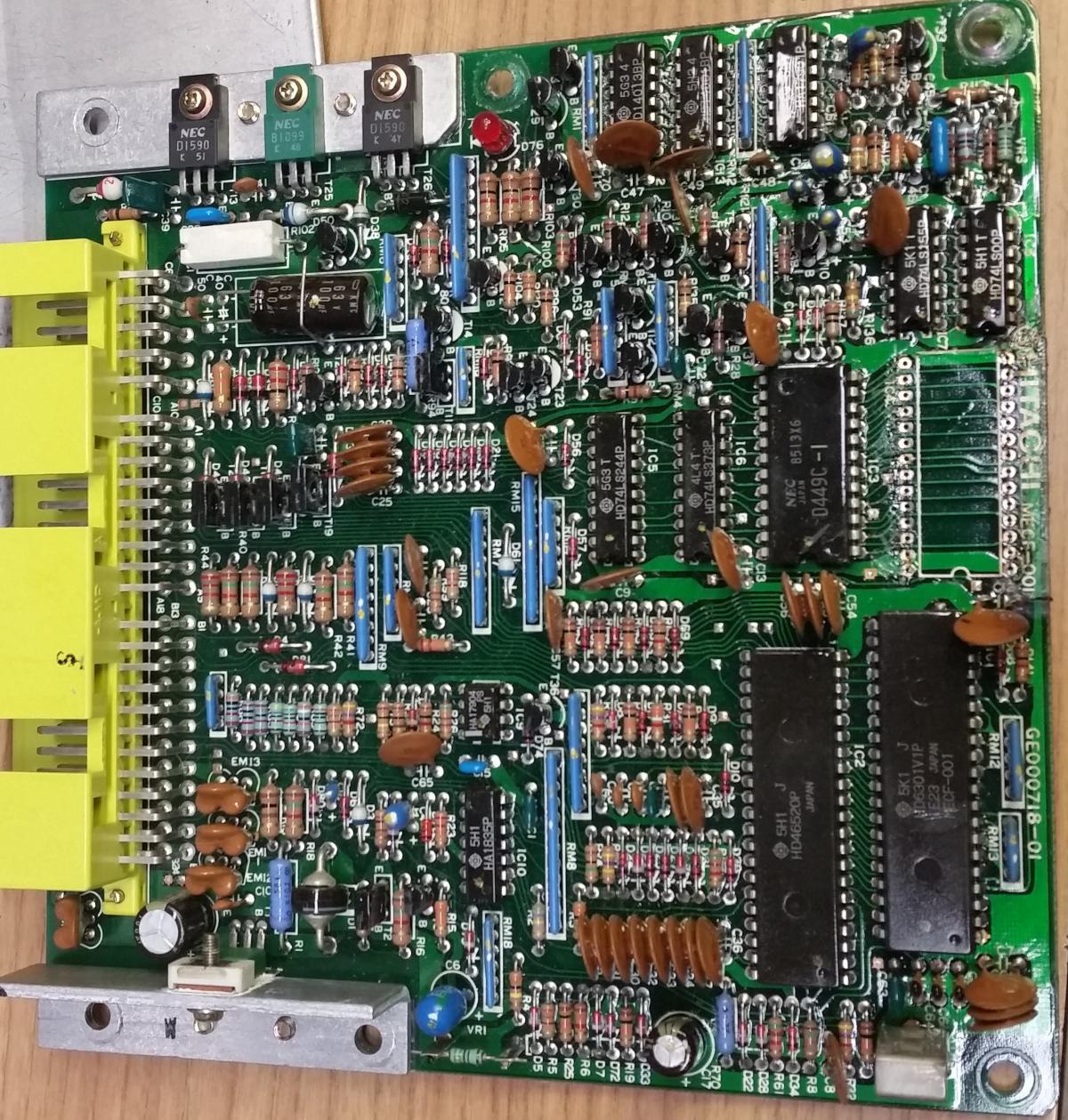
Yes, there is a crystal right there. I'll check the frequency. I have one of those plug in breadboards, so it is possible to pull a cpu and wire it up on one of those without having to spend for a PCB. I can try tracing out the LED. I also want to figure out which wires on which connectors are power and GND.
-
DaveT replied to pzookey's topic in 1990 to Present Legacy, Impreza, Outback, Forester, Baja, WRX&WrxSTI, SVXyep, either one of those pretty much make it clear. Add in the WOT on top of the other manageable conditions, no doubt.
-
DaveT replied to hebrewhammer's topic in 1990 to Present Legacy, Impreza, Outback, Forester, Baja, WRX&WrxSTI, SVXYou might have to crop them or resize to get them under 2megabytes so the forum will allow upload.
-
That this is a swap, adds another layer of unknowns - as in correctly wired. The power travels that path, the white wire goes to one end of a link, the other end of the link goes to the battery through another wire. The link box pops right out of the slot on the tank, so it should be pretty easy to trace. Yes, sometimes someone is close enough to look, first hand is nearly always faster. The rectifiers are semiconductors that change the AC that the alternator generates into DC that can be used to charge a battery. They are inside the alternator. alternatorparts.com sells all of the internal parts for alternators.
-
Looks like MPFI to me. Turbo compresses air before it hits the throttle body / manifold, no? I think the turbo would be to the left & rear of the air tube in your picture, kind of hard to miss.
-
Headgaskets & reseal, expensive to pay a shop for. Lots of us on the forum have done it. I've done it a number of times. There are a lot of threads with all of the tips and tricks. Maybe not the best thing for a first time project, but if you have a space and the time, you will learn a lot.
-
11.5V is not charging, it's running off the battery. You want at least 13.8V at the battery terminals to be charging in a car situation. Check the heavy white wire that connects to the output terminal of the alternator, and where it goes into the fusible link box on the coolant recovery tank. Check the link, and the wire to the battery clamp. Looking for good solid connections. For reference & battery checking - Battery at rest readings - 12.0V = fully discharged, 12.6V = fully charged. Battery at rest means no loads or charging for at least 24 hours.
-
-
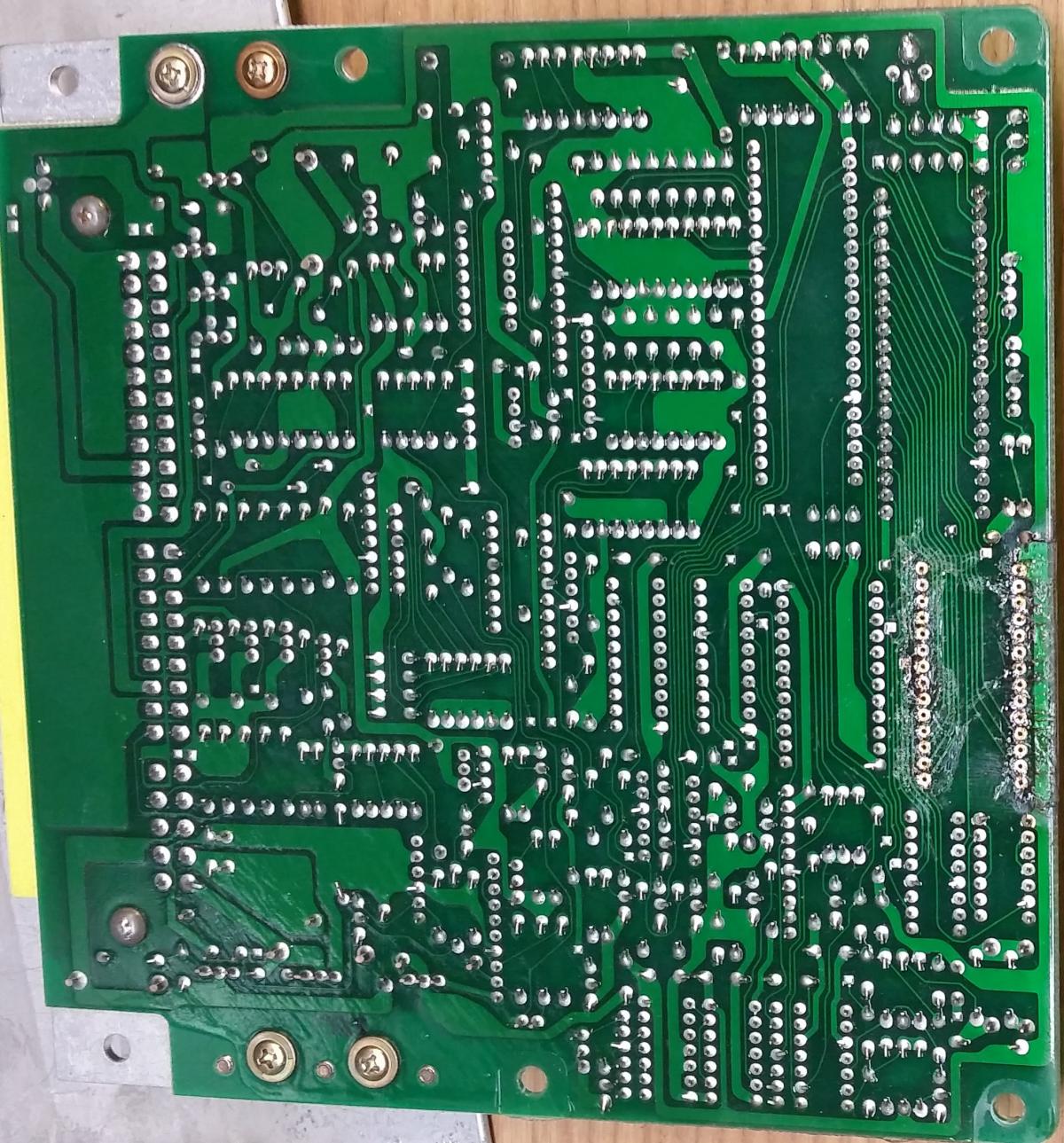
Some address and data lines: EPROM CPU D0 11 37 D1 12 36 D2 13 35 D3 15 34 D4 16 33 D5 17 32 D6 18 31 D7 19 30 EPROM CPU A11 23 26 A10 21 27 A9 24 28 A8 25 29 I'm thinking these are high byte memory address lines. A0 of the EPROM goes to pin 9 of the LS373 8bit latch It's the Q4 output. I haven't found where the D4 input is. The damn conformal coating makes tracing by ohmmeter difficult. I may just start removing more ICs.
-
-
-
Depending on which data sheet I look at, I see also that pins 4 & 5 may select modes. The smaller data sheet I posted the part number matches 100%. The big one covers many more ? or slightly different? ones. I just rechecked the 3 pins, 8,9,10 and yes, they are tied high by 1.00K resistors. 4 & 5 measure 4-6K to either VCC or GND, so I'll have todo some sort of powered up test to determine them.
-
Hard to be 100% sure with so little info, but plan on replacing the head gaskets. Over normal temperature while low on coolant almost always causes head gasket failure. Repeated, guarantees it. As long as it hasn't been really cooked bad, the reseal job should fix it. Miles on a decently maintained Subaru don't mean nearly as much to me as body condition.
-
-
-
DaveT replied to hebrewhammer's topic in 1990 to Present Legacy, Impreza, Outback, Forester, Baja, WRX&WrxSTI, SVXMight as well try it. If the puller is strong enough and the bearing isn't super tight, save a bunch of time.
-